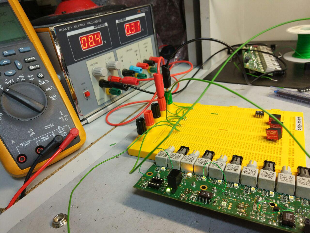
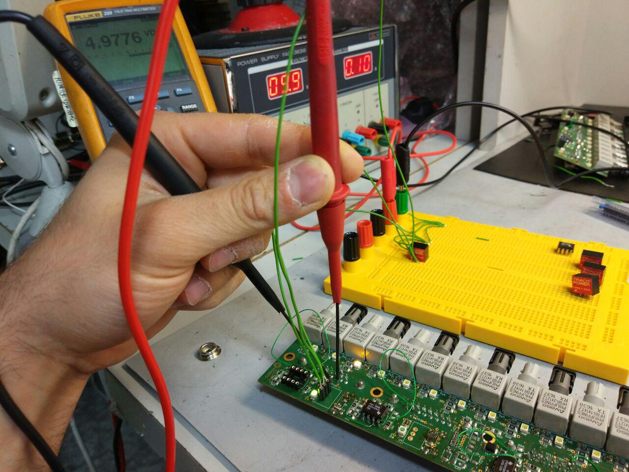
Hello Folks

I am running out of ideas. I have designed a PCB with three Traco Power
switching regulators: TSR1 2450. After an initial test with the three SW
Regulators mounted, the PCB was broken because an overcurrent. Then I
isolated one SW regulator in a Protoboard (see Pic1) and the SW
regulator regulated the voltage rightly (Vin=10V, Vout=5V).

However when I mounted again the same regulator on the board (see Pic
2), the SW regulator did not work properly and I measured the output
voltage and it was the same voltage (aprox.) like the input voltage
(Vin=10V, Vout=9.6V). It is like the regulator short circuits the input
with the output. Anyone has any idea about what can it be happening?.

Thanks in advance.
Attached files:
-

TSR1_2450_pin.png
19 KB

Kike wrote:
> voltage and it was the same voltage (aprox.) like the input voltage
> (Vin=10V, Vout=9.6V).

Please verify that you are using the proper pins.
I can't tell loking at pic1 - it would be easier if you could use
different wire colors.
Hey Kike,

at least there is one thing that you have to realize
(but maybe there are two of them ...):

Certainly there´s a "little bit" more resistance,
both at the "power"-lines, as at the eventual additional
measurement laces...

(...and - what surely could be the case - the two circuits
could simply be "a little" different... what could be
surprisingly hard to find out).

Please check that thoroughly.
lasag wrote:
> Please verify that you are using the proper pins.

Dear lasag, did you mean a mix-up of two pins
only at the PCB (and right pinning at the BBoard)?
Homo Habilis wrote:
> lasag wrote:
>> Please verify that you are using the proper pins.
>
> Dear lasag, did you mean a mix-up of two pins
> only at the PCB (and right pinning at the BBoard)?
Yep.  Also, I think there is a remark (24V) near the front of the board
and another (5V) in the depth - which is contrary to OUT-GND-IN (front
to back) pin order of the regulator if mounted as shown in pic2.
I am unsing the proper pins verify a lot of times...

I figure out that there is a problem with the impedance of the power
planes:

Pic1 with the yellow board: Z(24V-GND) = 100K. Notice that there is not
short circuit but the Impedance is very low...
Pic2 without the yellow board and the SW regulator mounted directly on
the PCB: Z(24V-GND) = 200Ohm.

I guess that there is design failure anyway,  but I would like to know
if there is anyway to increase the plane impedance to solve this problem
momentarily and go on with other tests...

thanks in advance.
Kike wrote:
> I am unsing the proper pins verify a lot of times...

I have no other explanation for the reported symptoms(*). Limiting the
current from the power supply, it should be no problem to mount the
regulator rotated by 180° - just to be shure.

Without an actual schematic and PCB layout, it is impossible to give you
any other hint.

(*) variable input resistance by mouning the correct pins either by wire
or directly would indicate a failure whithin the socket/board soldering.
The SW regulator was mounted in the wrong way on the PCB and there was a
mess because that....Begginer failure :-( Now it works perfectly :-)

Greetings!!
Please log in before posting. Registration is free and takes only a minute.
Existing account
Do you have a Google/GoogleMail account? No registration required!
Log in with Google account
Log in with Google account
No account? Register here.