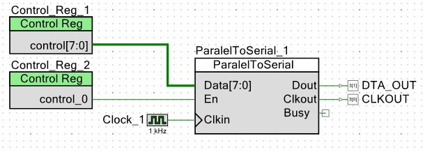
Hi Friends I am trying to make a simple spi module with verilog. After I get the Enable signal, I want to send the 8 bit data in series. I've never worked with a verilog before. I wrote a simple code but I do not know how to generate the clock signal. this is my Code;
1 | `include "cypress.v" |
2 | //`#end` -- edit above this line, do not edit this line
|
3 | // Generated on 03/31/2017 at 15:12
|
4 | // Component: ParalelToSerial
|
5 | module ParalelToSerial ( |
6 | output Busy, |
7 | output Clkout, |
8 | output Dout, |
9 | input Clkin, |
10 | input [7:0] Data, |
11 | input En |
12 | );
|
13 | |
14 | //`#start body` -- edit after this line, do not edit this line
|
15 | reg busy; |
16 | reg dout; |
17 | reg clkout; |
18 | reg [3:0]cnt_spi; |
19 | reg clk_count; |
20 | |
21 | assign Busy = busy; |
22 | assign Dout = dout; |
23 | assign Clkout = clkout; |
24 | |
25 | always @ (negedge Clkin) |
26 | begin
|
27 | if(En == 1'b1 && busy == 1'b0) |
28 | begin
|
29 | clkout=1'b0; |
30 | dout=Data[cnt_spi]; |
31 | cnt_spi = cnt_spi + 1; |
32 | end
|
33 | |
34 | if(cnt_spi == 8) |
35 | busy=1'b0; |
36 | begin
|
37 | |
38 | end
|
39 | end
|
40 | |
41 | //`#end` -- edit above this line, do not edit this line
|
42 | endmodule
|
I will be glad if you help me. I'm just looking for a very simple example of spi.
:
Edited by Moderator
Ferhat Y. wrote: > I've never worked with a verilog before. So, why not starting with a flashing LED? > I am trying to make a simple spi module with verilog. After I get the > Enable signal, I want to send the 8 bit data in series. So you want to do an SPI master. For me the SS is missing there... > I wrote a simple code but I do not know how to generate the clock signal. You must 1. you must generate a scaled down SCLK "clock" signal out of the FPGA clock (which is usually round 50MHz) 2. you must generate a SS slaveselect signal and activate it before start of transaction 3. you must shift the data bit by bit on the MOSI line according to the phse of the SCLK 5. you must be aware that the SCLK is a simple output signal and NO clock(!!!) 4. you must set up a test bench to verify the behaviour of the whole thing But if I were you I would start with the LED and simulate it before going on real hardware. And be aware: the simulator is the HDL debugger!
:
Edited by Moderator
Hi @Ikmiller Thank you for the reply. Before starting this application, I did flashing LED. I'm testing it in real hardware. it works :) always @ (posedge Clkin) //1Khz Clock İnput begin if(counter== 500) begin counter=0; clkout = ~clkout; end end Now, I'm working on the PSoC devices. PSoCs have microcontroller and PGA. PGA is programmed with verilog like fpga. I don't need SS in my application because, I'm driving P10 LED panel, This panels only have DATAIN and CLOCKIN inputs. PSoC itself is doing frequency division. I only determine the clock frequency. PSoCs are being designed with blocks. (my design in the attachment) Now I need to write the contents of the Parallel_to_Serial module with verilog. I've sent a bit of bits to send dout=Data[cnt_spi]; I just need to generate the SCLK signal.And a little control. (Busy signal vs)
Ferhat Y. wrote: > I'm testing it in real hardware. it works :) Do a simulation on it. Just to learn how a simulation is done. You will find out, that there is a problem in your design: with a 1kHz clock you will not get the desired 1Hz flashing... > always @ (posedge Clkin) //1Khz Clock İnput Run the FPGA on a much higher clock. And from there generate clock enables for slower timings. > PSoCs are being designed with blocks. (my design in the attachment) > Now I need to write the contents of the Parallel_to_Serial module with > verilog. Its just a parallel loaded shift register. > I've sent a bit of bits to send dout=Data[cnt_spi]; I just need to > generate the SCLK signal. When looking at the picture: you already have a clock... > And a little control. (Busy signal vs) And it will be a good idea to add a sync signal (in SPI its called SS slaveselect) to the output.
:
Edited by Moderator
This example is with automatic shiftout. IIRC, it was not tested yet on real hardware. Only in simulator. Just found a more simple version. spi_master2.
:
Edited by User
Syntax $dumpfile("filename.vcd") $dumpvar //dumps all variables in the design. $dumpvar(1, top) //dumps all the variables in module top and below, but not modules instantiated in top. $dumpvar(2, top) //dumps all the variables in module top and 1 level below. $dumpvar(n, top) //dumps all the variables in module top and n-1 levels below. $dumpvar(0, top) // dumps all the variables in module top and all level below. $dumpon // initiates the dump. $dumpoff // stop dumping All the best :) VLSI Training at CETPA
In all honesty doing a SPI design is quite tricky. Usually a state machine and edge detection is used along with counters (for which bit is coming in). This is not a trivial design. Be forewarned.
Don't the PSoCs offer an SPI master module which you could easily use within your main firmware (written in C)?
http://www.cypress.com/training/psoc-video-tutorial-series-how-create-custom-components I have used recently the SPI Master component build in in Creator. It works fine for LEDs, just you need to assign MISO and SS to any unused pins.
Ananthoji Vineeth Kumar wrote: > I want spi code with testbench in verilog Sorry to say that I only can offer one in VHDL: http://www.lothar-miller.de/s9y/categories/45-SPI-Master But after starting thinking it its fairly easy to translate it to Verilog. BTW: Did you read the posts in this thread? Mark the correct answer with a cross: [ ] No
:
Edited by Moderator
I provide these all the time! These are typically amazing good quality lace wigs,bob wigs https://youtu.be/3KO3e4I3_24. I obtained contemplating I get lots of compliments on them every day from good friends, academics, even strangers! :)