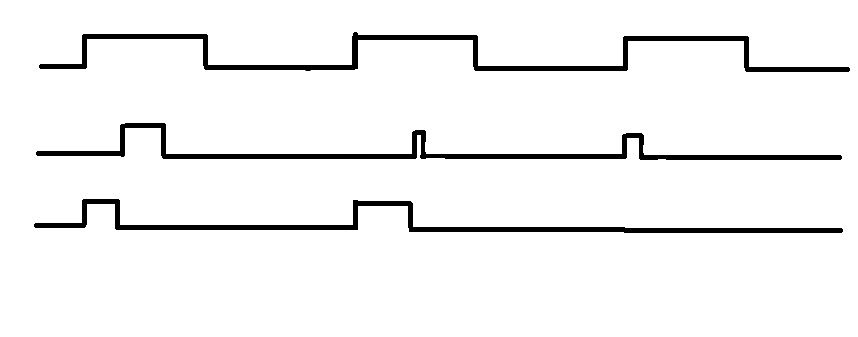
Hi,
Im currently making project of protection for voltage inverter. I know
my problem is probably too simple to even post it but im just stuck..
Anyway im using fpga because i need fast and parallel work. My problem
looks like this:
(attachment)
lets say first 2 signals are inputs and the last one is output.
Output will be exacly as first input when 2nd signal is zero.
However if 2nd signal is 1 then output turns 0, but also output signals
doesnt bring itself back to 1 until 1st signal isnt rising to 1.

I know i should use SRFF but i have problem with clock signal.. how
should it look? it should have rising edge whenever signal 1, negated
signal 1 or signal 2 is rising.
Attached files:
-

crap.jpg
16 KB
Something like this?

states1:
passthrough
holdoff

states2:
was_low
was_hi

for s1:

if(s1==holdoff)
  if(s2==was_low)
    if(in1&&(!in2))
      s1<=passthrough;
    else
      s1<=holdoff;
else if(s1==passthrough)
  if(in2)
    s1<=holdoff;

for s2:

if((s2==was_low) && in1)
  s2<=was_hi;
else if((s2==was_hi) && !in1)
  s2<=was_lo;

and use s1 to control a mux from
{in1,0} to out

Ideally the processes for s1 and s2 should be clocked
by the same clock (it's the least trouble) and it'll
better be a lot faster than in1, otherwise edge detection might not
work.

You could also try to use a single ff that is clocked by in1
which sets <=1 on every up edge,
and use in2 as a reset.
Use the ffs output to control the mux so you get the falling edge.
For this you'll have to know if the in1 is usable as a clock
(duty cycle,frequency..)
and how glitchy in2 is...
Thank You very much,
yeah my input 1 is PWM signal and input 2 is just signal from comparator
telling me is current too high currently so its glitchy. I used mux and
ff, that should be enough :) I had mux in my mind but i somehow stayed
with diffrent solution. Thank you again, now its working :)
Kam S. wrote:
> I know i should use SRFF but i have problem with clock signal.. how
> should it look? it should have rising edge whenever signal 1, negated
> signal 1 or signal 2 is rising.

Simply take the PWM signal to clock your SRFF.
Hard wire a high to S(ET) and a low to R(ESET) inputs.
Use the second signal (comparator output) as asynchronous clear (you
might have to invert it if the SRFF has a CLK_N input).
Please log in before posting. Registration is free and takes only a minute.
Existing account
Do you have a Google/GoogleMail account? No registration required!
Log in with Google account
Log in with Google account
No account? Register here.