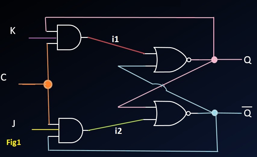

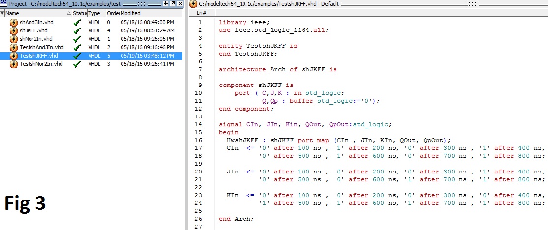
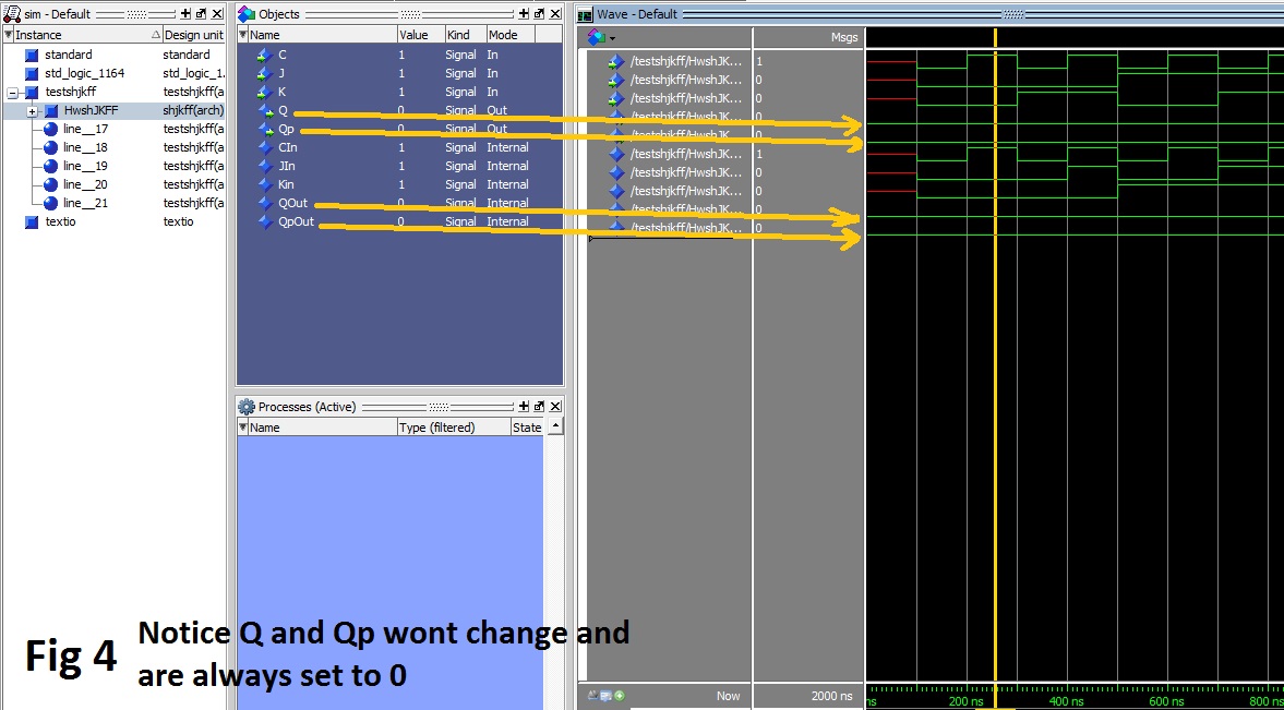
Hello. As you can see in the figure 1, We can make a JK flipflop with 2
ANDs and 2 NORs and two internal signals.

So I've written a very simple code in ModelSim to make and simulate a JK
FlipFlop (Figure 2 - the code and Figure 3 - the benchmark which I
simulated it in the software) but the problem is, the output of the
flipflop is always same. (Figure 4)

What is wrong with the outputs?

I know there are different ways to make a JK FlipFlop, but this is the
way that I should make as a part of an other project, yet I have no clue
why the outputs are not working. (Pictures are attached to this post)

IMPORTANT NOTE: Please ignore the "shAnd3In" and "shNor2In" components
in the figure 2.
From a first glance I would say, that the circuit isn't a JK-FF as it
lacks feedbacks from the outputs to the input-and-gates of the
complementary parts.

You omitted specification of the FF you want to create. What kind of
JK-FF would you like to create? In other words: With which truth value
table? Or let me express my question as: When do you want it change its
state, and when not?
seems all hope is gone in the Moment q equals qn, the FF will never
recover from this state. Try Initial values to resolves this invalid
state.
Attached files:
-

F5.jpg
23 KB
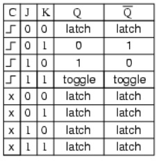
Staubfänger wrote:
> From a first glance I would say, that the circuit isn't a JK-FF as it
> lacks feedbacks from the outputs to the input-and-gates of the
> complementary parts.
>
> You omitted specification of the FF you want to create. What kind of
> JK-FF would you like to create? In other words: With which truth value
> table? Or let me express my question as: When do you want it change its
> state, and when not?

Well, I want this JK FlipFlop change states when the clock value goes
from 0 to 1. The truth table should be something like the new picture
that I've attched in this post (F5.jpg).
crystal bowl wrote:
> seems all hope is gone in the Moment q equals qn, the FF will never
> recover from this state. Try Initial values to resolves this invalid
> state.

Would you explaine more? I'm afraid I didn't catch what you extacly
mean.
Dan N. wrote:
> crystal bowl wrote:
>> seems all hope is gone in the Moment q equals qn, the FF will never
>> recover from this state. Try Initial values to resolves this invalid
>> state.
>
> Would you explaine more? I'm afraid I didn't catch what you extacly
> mean.

Presumed crystal's allowance I try to explain instead of him:

The state of Q = not Q = 0 isn't a legal stationary state. Q and not Q
have to have different states in every case. (Despite very short moments
where there are about to change).
Starting the simulation with Q = not Q = 0 caused a lock in that state.
The internal signals i1 and i2 could never change to 1 (as the and would
only go to 1 if all inputs are 1). So the state wont change whatever you
do at clock or J or K.
My English is sort of strange today, sorry. :-) Should have re-read it
before posting.


Presumed crystal's allowance I'll try to explain instead of him:

The state of Q = not Q = 0 isn't a valid stationary state. Q and not Q
have to have different states at every moment. (Despite very short
moments
when they are about to change).

Starting the simulation with Q = not Q = 0 causes a lock in that state.
The internal signals i1 and i2 could never change to 1 (as the and-gate
would only output a 1, if all inputs are 1). So the state wont change,
whatever you do at clock or J or K inputs.

Hope, that's a little bit better.
Attached files:
-

F6.jpg
75 KB
Well I set the initial value of Q = 0 and Qp (or the "not Q") = 1,
unfortunately the state of Q is always 0 and the Qp is alwats 1 (still
none of them are changing)

To be more clear, I've replaced this piece of code:
1 | port ( C,J,K : in std_logic:='1'; |
2 | Q,Qp : buffer std_logic:='0'); |
to this:
1 | port ( C,J,K : in std_logic:='1'; |
2 | Q : buffer std_logic:='1' ; Qp : buffer std_logic:='0'); |
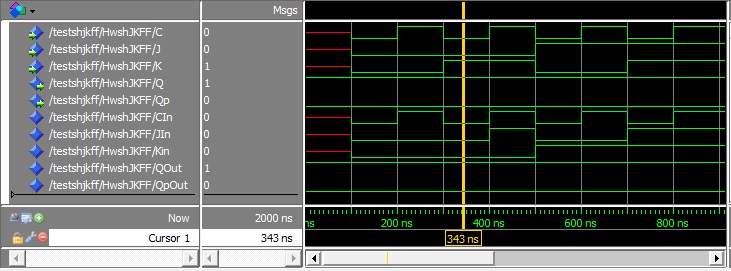
And the new simulation result is attached to this post (F6.jpg).
Unfortunately I am a bit busy now, so let me give you some generic
advice right now.

1. You still have undefined signals (as you may notice red lines in your
simulation output).

2. Consider uninitialized signals (f.e. internal i1 and i2) and C,J,K in
your testbench. Take care that these initializations are not
contradictory as set i1 or i2 to an output value which could not occur
at the very combination of the and-gates inputs.

3. I'm not used to your very simulation software. But in case of using
feedbacks it's an important question if simulate real circuit or only
the idealized circuit (there is a formal expression but I don't remember
it right now). The former is done, if you do a "Post-Place-N-Route"
simulation as there the real devices delay is considered.
The latter does not consider that, which is good for circuits which are
only combinatorial (which do not contain feedbacks). If you
intentionally want to do the latter, you have to provide an architecture
which explicitly describes delays.

4. Point 3 is related also to your stimulus. Your edges, that of clk, j
and k occur seemingly at the very same point in time. This leads likely
to unexpected results - which in detail depend on the simulation
software implementation. It would be, formally, better to change J or K
before changing clk. Doing it at the same moment gives formally a
contradictory or at least dubious condition for the gates.

5. I'm still convinced that the structure is not a JK-FF. I wrote this
in my first post and described the deviation from the form I remember.
Please check that.

I hope that helps you further.
If anybody else sees any error in my post, please feel free to correct
it.

Good luck.
Staubfänger wrote:
> Unfortunately I am a bit busy now, so let me give you some generic
> advice right now.
>
> 1. You still have undefined signals (as you may notice red lines in your
> simulation output).
>
> 2. Consider uninitialized signals (f.e. internal i1 and i2) and C,J,K in
> your testbench. Take care that these initializations are not
> contradictory as set i1 or i2 to an output value which could not occur
> at the very combination of the and-gates inputs.
>
> 3. I'm not used to your very simulation software. But in case of using
> feedbacks it's an important question if simulate real circuit or only
> the idealized circuit (there is a formal expression but I don't remember
> it right now). The former is done, if you do a "Post-Place-N-Route"
> simulation as there the real devices delay is considered.
> The latter does not consider that, which is good for circuits which are
> only combinatorial (which do not contain feedbacks). If you
> intentionally want to do the latter, you have to provide an architecture
> which explicitly describes delays.
>
> 4. Point 3 is related also to your stimulus. Your edges, that of clk, j
> and k occur seemingly at the very same point in time. This leads likely
> to unexpected results - which in detail depend on the simulation
> software implementation. It would be, formally, better to change J or K
> before changing clk. Doing it at the same moment gives formally a
> contradictory or at least dubious condition for the gates.
>
> 5. I'm still convinced that the structure is not a JK-FF. I wrote this
> in my first post and described the deviation from the form I remember.
> Please check that.
>
> I hope that helps you further.
> If anybody else sees any error in my post, please feel free to correct
> it.
>
> Good luck.

1: fixed them by adding them predefined values, no changes.
2: they should get value when simualtion gets started, still predifining
didn't work.
3: Yes, that is right, may be it is better to use a reallife kit. But
our teacher asked us doing it on the software and even he himself don't
know what is wrong with it.
4,5: Well according to the book and what our teacher said, this is a JK
latch.

Thanks for the replies, the project got canceled.
Problem fixed, As it is a bit long and detailed, I encourage people to
see how it got fixed here:
http://www.alteraforum.com/forum/showthread.php?t=52409 .

Thanks for your replies.
Goodbye.