Hello,

I want to design 8x1 multiplexer. But, I just only have 5 options of
input, which are freq1, freq2, freq3, freq4, and freq5. Is it possible
to design it with only just have 5 options of input?

Thank you.
Min_ah wrote:
> Is it possible to design it with only just have 5 options of input?
Its like dricng a car possible to speed up to 200km/h only with
125km/h...

> Is it possible to design it with only just have 5 options of input?
Yes, if you use only 5 inputs, then the remaining 3 are unused and tied
to '0'. Or they are the "when others" case and mirror one of the
selections...

> 5 options of input, which are freq1, freq2, freq3, freq4, and freq5.
You want to multiplex (clock) frequencies?
Min_ah wrote:
> Multiplexe_8x1.docx (11.1 KB, 3 downloads)
I'm sorry, I will not download a docx file. That is not a format to
interchange documents. Try a pdf instead...

> Yes, I want to multiplex clock frequency.
Usually that is a very, very bad idea. If you are a beginner you should
not do a design needing 5 different clocks. It will break your bones.

To get a clearer picture write as much information as possible. What do
you need thes clocks for? Are that really clocks? Where do the signals
come from? Where do they go to?
Attached files:
-

Multiplexer.JPG
220 KB
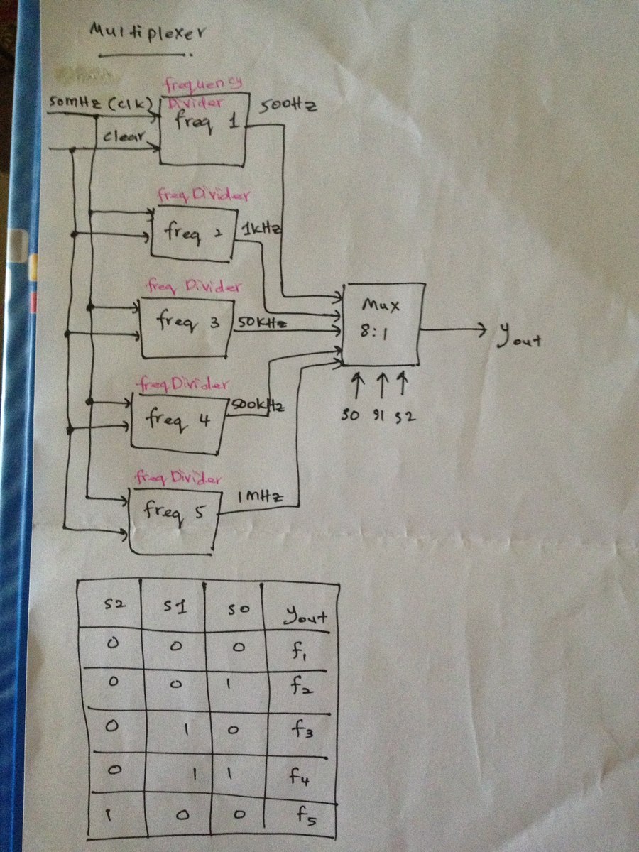
I need to design the Multiplexer like the picture I give above.
it's quite straight-forward to describe such a multiplexer in VHDL. When
I google the words "VHDL multiplexer" pretty much every link I get gives
a useable guideline. If I follow two or three links, then I even get a
source which can get copied without much modification.

But as Lothar already mentioned: multiplexing Clock signals in a real
design will not work like that (even if the simulation may tell you
something different). With such a Multiplexer you can deliver a logic
signal Yout as output. But a logic signal and a Clock are something
different inside an FPGA (they do not even share the same signal lines).
If you want to run it in real hardware, then you'll need a different
approach.
Min_ah wrote:
> I need to design the Multiplexer like the picture I give above.
This is (as already said) NOT a way to generate signals for use as a
clock inside a FPGA.
Instead I urge you to have a look for the clock enable strategy: only
1 clock (about 50..100MHz) throughout the whole design and then a bunch
of signals generated by counters, each signal active for a single clock
cycle.
Please log in before posting. Registration is free and takes only a minute.
Existing account
Do you have a Google/GoogleMail account? No registration required!
Log in with Google account
Log in with Google account
No account? Register here.