Hi guys, Since UFM in the Machxo2 seems to difficult to setup, I broke
out the arduino and with a little help figured out how to write 2 bytes
to memory and read those bytes, i also downloaded Lothar Miller's Spi
Master and got it talking to an spi encoder by a single 16 bit transfer
on the Machxo2. Now the hard part, to read my 2 bytes i have to send
Ox-D2,00,00,00,00,00,00,00,00+ read byte1, 00 + read byte2. To write
those 2 bytes I have to send 0x82, 00,00,00, my byte, my byte. I know i
need to build a state machine, i need ChipSelect to stay low durring the
whole transfer. this one is a little tougher.
Chris C. wrote:
> I know i need to build a state machine,
Keep things simple and don't worry about big names: each counter is a
state machine...

> i need ChipSelect to stay low durring the whole transfer.
That easy: you must control SS in your own FSM. Set it low in the first
state and set it high after the last...

> this one is a little tougher.
It istn't. Its just about learning.
First step is to set up a "top level" module and to use the SPI unit as
a component inside your top level entity. Then you control that SPI
module with those three ports you commented out:
   -- TX_Data  : in  STD_LOGIC_VECTOR (length-1 downto 0); -- Send data
   -- TX_Start : in  STD_LOGIC;
   -- TX_Done  : out STD_LOGIC;
In that new top level FSM you simply set up TX_Data and set TX_Start to
'1'. Then in the next state you set TX_Start to '0' and wait for TX_Done
to go '1'. If so, you set up TX_Data and set TX_Start to '1' and so
forth...
1 | entity SPI_top_level is... |
2 | :
|
3 | end SPI_top_level; |
4 | |
5 | architecture Behavioral of SPI_top_level is |
6 | signal TX_Data : STD_LOGIC_VECTOR (length-1 downto 0); |
7 | signal TX_Start : STD_LOGIC; |
8 | signal TX_Done : STD_LOGIC; |
9 | signal MOSI ... |
10 | signal MISO ... |
11 | |
12 | signal transmitstate : integer := 0: |
13 | |
14 | component SPI_Master is -- SPI-Modus 0: CPOL=0, CPHA=0 |
15 | Generic ( Quartz_Clock : integer := 50000000; -- Hertz |
16 | SPI_Clock_Speed : integer := 2500000; -- Hertz / calculate reload-value for clock divider |
17 | length : integer := 8 -- Number of bits to be transmited |
18 | );
|
19 | Port ( TX_Data : in STD_LOGIC_VECTOR (length-1 downto 0); -- Send data |
20 | RX_Data : out STD_LOGIC_VECTOR (length-1 downto 0); -- recieve data |
21 | MOSI : out STD_LOGIC; |
22 | MISO : in STD_LOGIC; |
23 | SCLK : out STD_LOGIC; |
24 | SS : out STD_LOGIC; |
25 | TX_Start : in STD_LOGIC; |
26 | TX_Done : out STD_LOGIC; |
27 | clk : in STD_LOGIC |
28 | );
|
29 | end component; |
30 | :
|
31 | :
|
32 | :
|
33 | begin
|
34 | SPI_Controller : SPI_Master port map (...); |
35 | :
|
36 | process begin |
37 | wait until rising_edge(clk); -- the one and oly clock |
38 | :
|
39 | case transmitstate is |
40 | when 0 => SS <= '0'; -- slave select |
41 | transmitstate <= 1; |
42 | |
43 | when 1 => TX_Data <= x"D2"; |
44 | TX_Start<= '1'; |
45 | transmitstate <= 2; |
46 | |
47 | when 2 => TX_Start<= '0'; |
48 | if TX_Done='1' then |
49 | TX_Data <= x"00"; |
50 | TX_Start<= '1'; |
51 | transmitstate <= 3; |
52 | end if; |
53 | |
54 | |
55 | :
|
56 | :
|
57 | :
|
58 | |
59 | |
60 | when 8 => TX_Start<= '0'; |
61 | if TX_Done='1' then |
62 | TX_Data <= readbyte1; |
63 | TX_Start<= '1'; |
64 | transmitstate <= 9; |
65 | end if; |
66 | |
67 | when 9 => TX_Start<= '0'; |
68 | if TX_Done='1' then |
69 | TX_Data <= readbyte2; |
70 | TX_Start<= '1'; |
71 | transmitstate <= 10; |
72 | end if; |
73 | |
74 | when 9 => TX_Start<= '0'; |
75 | if TX_Done='1' then |
76 | transmitstate <= 10; |
77 | end if; |
78 | |
79 | when 10 => SS <= '1'; |
80 | transmitstate <= 0; |
81 | :
|
82 | :
|
Got the idea?
ive been trying similar code, with mine i was only getting d2 and 2x00
bytes out then it would reset,not sure why. With the the one you just
posted, im getting all of the clocks and cs is working, but no d2 on
mosi.
This time I switched a few things around and got it to throw out My xd2,
but only 3 bytes follow till it resets back to xd2?
I Figured it out! TX_DONE was 3 clock pulses wide, so i sent it through
a single edge detector and voila, everything is showing perfectly out to
the logic analyzer!

tx_done <= flipflops(0) and not flipflops(1);
  ------ Administration --------
   PROCESS(clk)  --  single edge based interupt
   BEGIN
    IF rising_edge(clk) THEN
      flipflops(0) <= tx_done1;
      flipflops(1) <= flipflops(0);
    END IF;
  END PROCESS;
Attached files:
-

WF_testbenchtryspi_fail.PNG
40 KB -

WF_testbenchtryspi_ok.PNG
42 KB
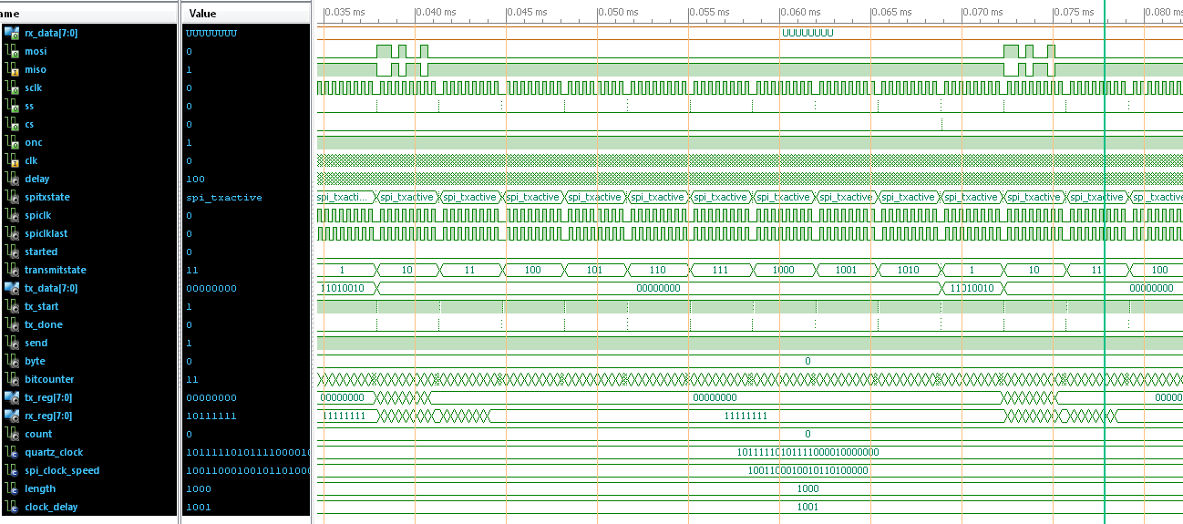
Chris C. wrote:
> This time I switched a few things around and got it to throw out My xd2,
> but only 3 bytes follow till it resets back to xd2?
You are right. Run a simulation on it. Then you will see the problem
easily...

It is a problem in handshaking. After a minor chage it looks ok (see
Waveform from simulation):
1 | :
|
2 | :
|
3 | when spi_etx => |
4 | SS <= '1'; -- disable Slave Select |
5 | TX_Done <= '1'; |
6 | -- if(TX_Start = '0') then
|
7 | spitxstate <= spi_stx; |
8 | -- end if;
|
9 | end case; |
10 | :
|
11 | :
|
Chris C. wrote:
> I Figured it out! TX_DONE was 3 clock pulses wide, so i sent it through
> a single edge detector
You are right: a workaround can also fit things together... ;-)
Attached files:
-

spiresults.png
85 KB -

spiscan.png
85 KB
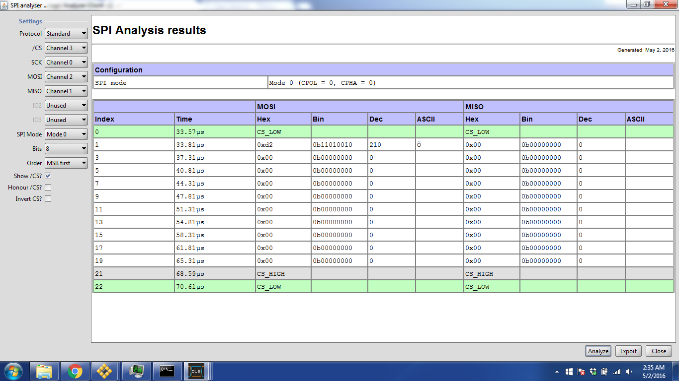

I had also tried that thinking it would help, but in silicon it was a
looped Cs and nothing else. Here she is.
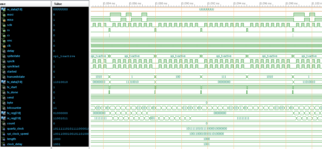
Thank YOU Lothar, one last thing, how can i reduce the delay between
bytes? right now from CS to CS is 4.42uS, i can shave off nearly 1uS by
removing some delay between bytes, Im limited to the 50mhz clk due to
all of my other process's in this project are timed with 50mhz, Far
toooo much to go back and recode. I have the Spi Clock at 25mhz, maxed
out.

Ahh, I see, I could also switch to 16 bit instead of 8 and cut it down
by 400ns.
Chris C. wrote:
> how can i reduce the delay between bytes?
At the moment these is one "SCLK idle cycle" hidden in the spitxstate
FSM. MAybe you get rid of that by setting the delay in spi_stx to 0:
1 | if(TX_Start = '1') then |
2 | spitxstate <= spi_txactive; |
3 | SS <= '0'; |
4 | delay <= 0; -- clock_delay; -- clock_delay adds a SCLK idle cycle here... |
5 | end if; |
> I have the Spi Clock at 25mhz, maxed out.
Up to now you use 2.5MHz...

For a 25MHz SPI clock you will need no prescaler at all, because with
every 50MHz clock the SPI clock must be toggled. You will have to look
close at the bit timing at this edge of speed.
Attached files:
-

25mhz.png
190 KB
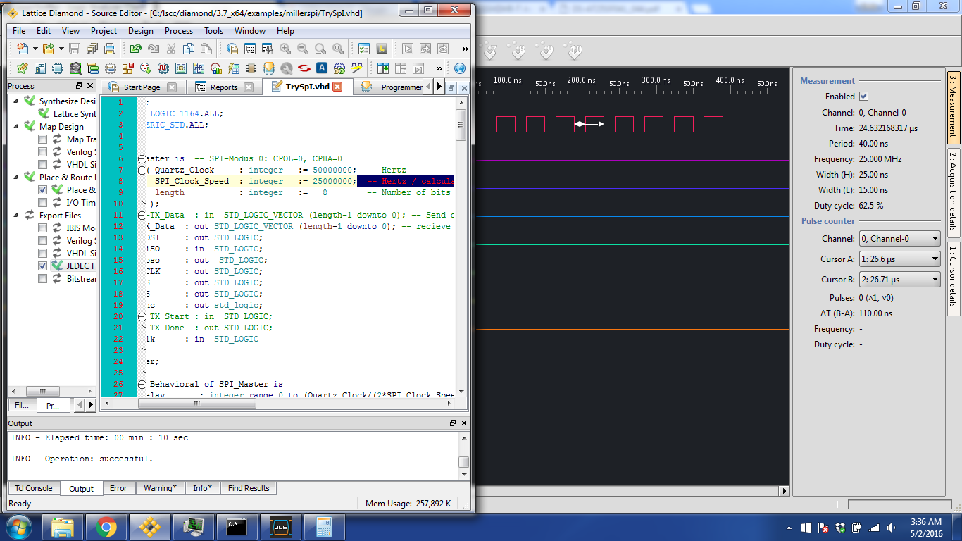
Will try more after work today, I gotta get a few hours of sleep lol

THis seems to be 25mhz 25ns high, 15ns low.
Chris C. wrote:
> THis seems to be 25mhz 25ns high, 15ns low.
You should have a look at the signal with an analog scope...
So sending and recieving is working, as long as im not trying to put
rx_reg into a "byte", strangely if i add "adjuster0 <= rx_reg;" right
after If tx_done = '1' then, suddenly i dont even get a response from
the flash, as seen on the logic analyzer.
Please log in before posting. Registration is free and takes only a minute.
Existing account
Do you have a Google/GoogleMail account? No registration required!
Log in with Google account
Log in with Google account
No account? Register here.