Help me please to write te vhdl code about the next delivery:
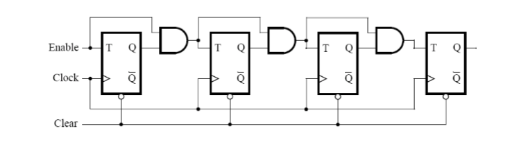
Consider the circuit in FigureA. It is a 4-bit synchronous counter,
which uses four T-type flip-flops. The counter increments the count
signal on each positive edge of the clock if the Enable signal is
asserted. The counter is reset to 0 by using the Reset signal. You need
to implement a 16-bit synchronous counter and alfter that you must
augment a vhdl file to use the pushbutton KEY0 as the Clock input,
switches SW1 and SW0 as Enable and Reset inputs, and 7-segment displays
HEX3-0 to display the hexadecimal count as your circuit operates.
Can i use 16t.flip_flop and Q(0)Q(1)Q(2)Q(3) for HEX0
Q(4)Q(5)Q(6)Q(7)Q(8) for HEX1
Q(9),Q(10),Q(11),Q(12) for HEX2
Q(13),Q(14),Q(15),Q(16) for HEX3 ?
LIBRARY ieee;
USE ieee.std_logic_1164.all;
ENTITY Counter IS
PORT (Enable, Clock, Clear: IN STD_LOGIC;
Q: STD_LOGIC_VECTOR(15 downto 0));
END Counter;
ARCHITECTURE Behavior OF Counter IS
SIGNAL count: STD_LOGIC_VECTOR(5 DOWNTO 0);
BEGIN
Q<= COUNT;
PROCESS(Clock,Clear)
BEGIN
IF Clear='1' THEN
count <= '000000000000000';
ELSIF Clock'EVENT AND Clock='1' THEN
???
-- I can't use Q <= Q+1;
END if
end process
end behavior;
Attached files:
-

FigureA.PNG
20 KB
Hello, you just have to describe a T-FF and then connect them as a
chain.

The description of the counter (just 8 bits):
1 | library ieee; |
2 | use ieee.std_logic_1164.all; |
3 | |
4 | entity counter_16bit is Port( |
5 | clock: in STD_LOGIC; |
6 | enable: in STD_LOGIC; |
7 | reset: in STD_LOGIC; |
8 | Q: out STD_LOGIC_VECTOR(7 downto 0)); |
9 | end counter_16bit; |
10 | |
11 | architecture behavior of counter_16bit is |
12 | |
13 | signal BIT_0, BIT_1, BIT_2, BIT_3, BIT_4, BIT_5, BIT_6, BIT_7: std_logic:= '0'; |
14 | |
15 | begin
|
16 | |
17 | Q <= BIT_7 & BIT_6 & BIT_5 & BIT_4 & BIT_3 & BIT_2 & BIT_1 & BIT_0; |
18 | |
19 | --FF_0:
|
20 | process (clock, enable, reset) |
21 | begin
|
22 | if reset = '1' then |
23 | BIT_0 <= '0'; |
24 | elsif rising_edge(clock) AND enable = '1' then |
25 | BIT_0 <= NOT BIT_0; |
26 | end if; |
27 | end process; |
28 | |
29 | --FF_1:
|
30 | process (clock, enable, reset) |
31 | begin
|
32 | if reset = '1' then |
33 | BIT_1 <= '0'; |
34 | elsif rising_edge(clock) AND enable = '1' AND BIT_0 = '1' then |
35 | BIT_1 <= NOT BIT_1; |
36 | end if; |
37 | end process; |
38 | |
39 | --FF_2:
|
40 | process (clock, enable, reset) |
41 | begin
|
42 | if reset = '1' then |
43 | BIT_2 <= '0'; |
44 | elsif rising_edge(clock) AND enable = '1' AND BIT_1 = '1' then |
45 | BIT_2 <= NOT BIT_2; |
46 | end if; |
47 | end process; |
48 | |
49 | --FF_3:
|
50 | process (clock, enable, reset) |
51 | begin
|
52 | if reset = '1' then |
53 | BIT_3 <= '0'; |
54 | elsif rising_edge(clock) AND enable = '1' AND BIT_2 = '1' then |
55 | BIT_3 <= NOT BIT_3; |
56 | end if; |
57 | end process; |
58 | |
59 | --FF_4:
|
60 | process (clock, enable, reset) |
61 | begin
|
62 | if reset = '1' then |
63 | BIT_4 <= '0'; |
64 | elsif rising_edge(clock) AND enable = '1' AND BIT_3 = '1' then |
65 | BIT_4 <= NOT BIT_4; |
66 | end if; |
67 | end process; |
68 | |
69 | --FF_5:
|
70 | process (clock, enable, reset) |
71 | begin
|
72 | if reset = '1' then |
73 | BIT_5 <= '0'; |
74 | elsif rising_edge(clock) AND enable = '1' AND BIT_4 = '1' then |
75 | BIT_5 <= NOT BIT_5; |
76 | end if; |
77 | end process; |
78 | |
79 | --FF_6:
|
80 | process (clock, enable, reset) |
81 | begin
|
82 | if reset = '1' then |
83 | BIT_6 <= '0'; |
84 | elsif rising_edge(clock) AND enable = '1' AND BIT_5 = '1' then |
85 | BIT_6 <= NOT BIT_6; |
86 | end if; |
87 | end process; |
88 | |
89 | --FF_7:
|
90 | process (clock, enable, reset) |
91 | begin
|
92 | if reset = '1' then |
93 | BIT_7 <= '0'; |
94 | elsif rising_edge(clock) AND enable = '1' AND BIT_6 = '1' then |
95 | BIT_7 <= NOT BIT_7; |
96 | end if; |
97 | end process; |
98 | |
99 | end behavior; |
And here the testbench:
1 | LIBRARY ieee; |
2 | USE ieee.std_logic_1164.ALL; |
3 | use IEEE.numeric_std.all; |
4 | |
5 | ENTITY counter_16bit_bench IS |
6 | END counter_16bit_bench; |
7 | |
8 | ARCHITECTURE behavior OF counter_16bit_bench IS |
9 | |
10 | COMPONENT counter_16bit is Port( |
11 | clock: in STD_LOGIC; |
12 | enable: in STD_LOGIC; |
13 | reset: in STD_LOGIC; |
14 | Q: out STD_LOGIC_VECTOR(7 downto 0)); |
15 | END COMPONENT; |
16 | |
17 | signal clock, enable, reset : std_logic := '0'; |
18 | signal Q : std_logic_vector(7 downto 0); |
19 | |
20 | constant clk_half_period : time := 5 ns; |
21 | signal clk: std_logic:='0'; |
22 | signal state: integer range 0 to 2:=0; |
23 | signal counter: integer range 0 to 63:=0; |
24 | |
25 | BEGIN
|
26 | |
27 | uut: counter_16bit PORT MAP ( |
28 | clock => clock, |
29 | enable => enable, |
30 | reset => reset, |
31 | Q => Q |
32 | );
|
33 | |
34 | clk <= not clk after clk_half_period; |
35 | |
36 | process begin |
37 | wait until rising_edge(clk); |
38 | |
39 | if state = 0 then |
40 | counter <= counter +1; |
41 | enable <= '1'; |
42 | clock <= to_unsigned(counter,6)(0); |
43 | if counter = 43 then |
44 | state <= state +1; |
45 | counter <= 0; |
46 | reset <= '1'; |
47 | end if; |
48 | elsif state = 1 then |
49 | reset <= '0'; |
50 | counter <= counter +1; |
51 | clock <= to_unsigned(counter,6)(0); |
52 | if counter = 13 then |
53 | enable <= '0'; |
54 | end if; |
55 | if counter = 27 then |
56 | state <= state +1; |
57 | enable <= '1'; |
58 | end if; |
59 | elsif state = 2 then |
60 | counter <= counter +1; |
61 | clock <= to_unsigned(counter,6)(0); |
62 | end if; |
63 | end process; |
64 | END; |
So ... i did the firt 8 bits of the work, now do the remaining half :-)
Gustl B. wrote:
> Hello, you just have to describe a T-FF and then connect them as a
> chain.


> So ... i did the firt 8 bits of the work, now do the remaining half :-)


Thanks,you re really kind. Your vhdl is really helpful!
Can you help me with the second part also, please?
augment a vhdl file to use the pushbutton KEY0 as the Clock input,
switches SW1 and SW0 as Enable and Reset inputs, and 7-segment displays
HEX3-0 to display the hexadecimal count as your circuit operates.
Hi!

to implement this, you need to write a constraint file! For this you
need the datasheet of your development board!
Additionally you need to write a a module to show each hex value on one
of the 7 segment digits!
this is ver easy with a case statement.
http://www.ics.uci.edu/~jmoorkan/vhdlref/cases.html

Why cant you use Q <= Q+1; ?
it would be way easier to do this this way and just care for the
overflow:
(ill do it for 8 bit)

signal counter : std_logic_vector (7 downto 0);
process(clk)
begin
if(rising_edge(clk)) then
if(counter="11111111) then
counter <= "00000000);
end if;
else
counter <= counter+1;
end if;
end process;

You can then just take the hex values: (for 16 bit counter)
signal hex3,hex2,hex1,hex0 : std_logic_vector (3 downto 0);

hex3 <= counter (15 downto 12);
hex2 <= counter (11 downto 8);
hex1 <= counter (7 downto 14);
hex0 <= counter (3 downto 0);

and map each to one 7_segment_decoder.

In your constraint file (.ucf) you just map your pins to the according
vhdl signals. If you need further help with this you need to provide
information what board you use!

if you use a button for clk input you should debounce it!
Ber 2. wrote:
>   -- I can't use Q <= Q+1;
What error messages do you get here?

>   -- I can't use Q <= Q+1;
This is due to 2 major problems:
1. You must use an arithmetic package for calculations!
2. You cannot read outputs, but for the 'Q+1' you need to do this. Do
you remember: you have a local counter signal named count for
counting?


Take the numeric_std and use an integer for counting:
1 | LIBRARY ieee; |
2 | USE ieee.std_logic_1164.all; |
3 | USE ieee.numeric_std.all; |
4 | |
5 | ENTITY Counter IS |
6 | PORT (Enable, Clock, Clear: IN STD_LOGIC; |
7 | Q: STD_LOGIC_VECTOR(15 downto 0)); |
8 | END Counter; |
9 | |
10 | ARCHITECTURE Behavior OF Counter IS |
11 | SIGNAL count: integer range 0 to 65535 := 0; |
12 | BEGIN
|
13 | Q <= std_logic_vector(to_unsigned(COUNT,16)); |
14 | |
15 | PROCESS(Clock,Clear) BEGIN |
16 | IF Clear='1' THEN |
17 | count <= 0; |
18 | ELSIF rising_edge(Clock) THEN |
19 | if count<65535 then |
20 | count <= count+1; |
21 | else -- wrap around |
22 | count <= 0; |
23 | end if; |
24 | END if |
25 | end process |
26 | end behavior; |
alexxk wrote:
> to implement this, you need to write a constraint file!
At least you must tell the toolchain what PINs you want to use and what
CLOCK frequency you have...
I think in this homework he should actually describe the single FF. And
perhaps use it as a component.
-gb- wrote:
> I think in this homework he should actually describe the single FF. And
> perhaps use it as a component.
That would be one of those stupid exercises leading to that extremely
chatty and unreadable "academic university VHDL".
Please log in before posting. Registration is free and takes only a minute.
Existing account
Do you have a Google/GoogleMail account? No registration required!
Log in with Google account
Log in with Google account
No account? Register here.