Implement filter in verilog

OP #4500097
Rate this post
useful
not useful
Dear all verilog seniors.

I am doing a small school project to design an image filter in verilog.

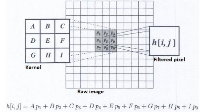
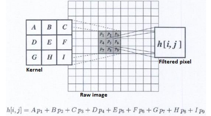
It can be summarized in this picture:
http://imageshack.com/a/img924/2851/Rt9ZI6.png

I have the following filter equation


h[i][j] = A*h[i-1][j-1] + B*h[i][j-1] + C*h[i+1][j-1] + D*h[i-1][j] + 
E*h[i][j] + F*h[i+1][j] + G*h[i-1][j+1] + H*h[i][j+1] + I*h[i+1][j+1]


However, I have no prior knowledge in RTL/verilog.


How should I proceed ?
Attached files:
Moderator (Company: Titel) #4500138
Rate this post
useful
not useful
Qq Q. wrote:
> How should I proceed ?
You shuld get a clear picture about the hardware you are using. Then 
you can describe this hardware with the Hardware Description 
Language Verilog.

So: What is the target of the design? Is it just for simulation? Where 
is the "raw image" stored? And where should the "filtered pixwls be 
stored? How can you access those memories? How big are those pictures? 
Can you fit them inside an FPGA?
Make a sketch with modules (adresscounter, memory, arithmetic unit) of 
this hardware. Think about necessary signals between the modules. Then 
you can try to desrcibe your task.

BTW:
If you never used Verilog before you should/must start with much simpler 
excersies: a flashing light, a chasing light, ...

Reply

Please log in before posting.

or

Log in with Google account

Registration is free and takes only a minute.

Register now