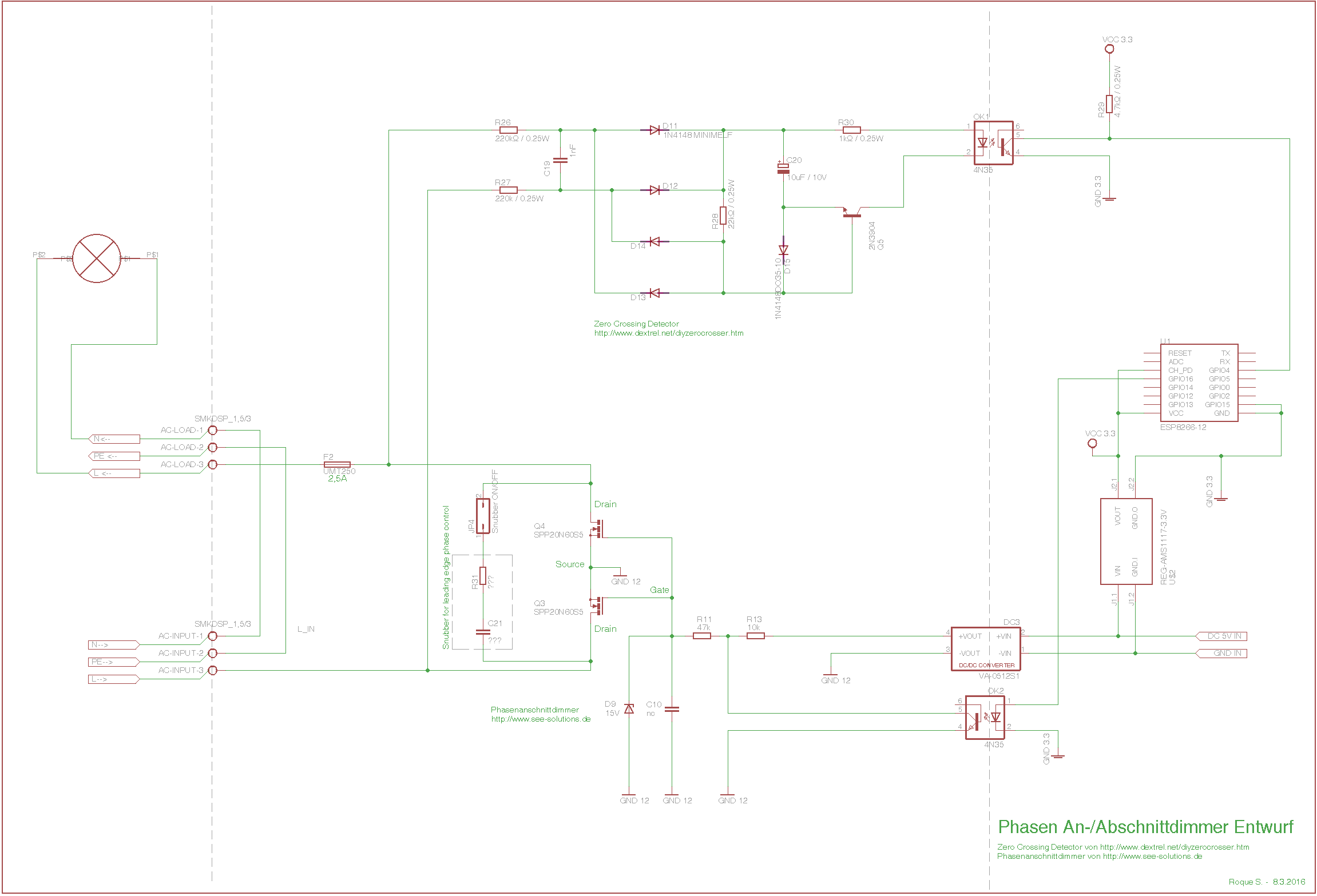
(Deutsche Version weiter unten / german translation at the end)

I want to build a trailing edge control / reverse phase control dimmer
controlled by Arduino or ESP8266. The dimmer is mainly meant for dimming
electronic transformers for 12V AC halogen lamps (example
http://www.osram.com/osram_com/products/electronics/electronic-control-gears-for-traditional-lighting/electronic-transformers-for-halogen-lamps/index.jsp).
My transformers are suitable for dimming only using trailing edge phase
control.

I copied most of the schematic from See-solutions.de (link in the
footer) and Dextrel (Link in the footer).

However i´m no circuitry expert and so hope for some hints and comments
from you.

# Did I insert the zero cross detector correctly?

# If I understand correctly, due it´s possible to switch the MOSFET´s on
and off at any time, it should also be possible to use the circuit for
leading edge phase control too (with changes in software). As I read for
leading edge phase control or inductive loads there is a snubber ciruit
needed (C21/R31). What is the right dimension for C21/R31? The snubber
needs to be as close as possible to the FET´s, right? Is there something
else needed besides the snubber? Does the snubber needed to be
switchable (JP4 for switching the snubber on in leading edge phase
control and switching of in trailing edge phase control), or is it ok to
just insert the snubber on both leading/trailing edge phase control.


# The gate voltage in the schematic is produced by a DC/DC converter. Is
it needed that the gate voltage is isolated from AC Mains side or would
It also be possible to supply the voltage from a simple capacitor power
supply ( between N and L) so I don´t need the DC/DC Converter.

# Compared with the original layout from
(http://www.see-solutions.de/projekte/2007_02%20sch_2.pdf) I replaced a
transistor with an optocoupler (OK2), did I inserted that correctly?

# The MOSFETS (SPP20N60S5)are made for heat efficiency, but they´re
released some time ago already, maybe someone knows a newer, better
choice or a cheaper alternative?

I´m looking forward to read your comments.

PS: Im in a 240V/50Hz and 240V/60Hz Area.

Greetz
Roque


German Translation:
Wie der Titel schon sagt möchte ich einen PhasenABschnittdimmer mit dem
ESP8266 realisieren. Ziel ist die dimmung von elektronischen NV Halogen
Trafos (die Trafos sind explizit nur für PhasenABschnittdimmung geeignet
und werden derzeit mit ELV DI22-2 gedimmt).

Hierzu habe ich mir die angefügte Schaltung von See Solutions (Link
siehe unten) und bei Dextrel (link siehe unten) zusammenkopiert.

Da ich in Sachen Schaltungstechnik wenig Erfahrung habe hoffe ich auf
ein paar Tips und von euch.

# Ist der Zero Cross Detector richtig integriert?

# Da man die MOSFETs ja zu einem beliebigen Zeitpunkt ein/ausschalten
kann könnte die Schaltung ja auch für einen PhasenANschnittdimmer
verwendet werden. So wie ich das verstanden habe ist für Phasenanschnitt
noch ein Snubber nötig (siehe C21 / R31). Wie müsste man den Snubber
dimensionieren? Dieser muss so nahe wie möglich an die FETs ran,
richtig? Wäre außer dem Snubber noch etwas nötig? Würde der Snubber im
Betrieb als PhasenABschnitt stören (JP4 wäre zum an und abschalten des
Snubbers falls ja).

# Die Spannung zum Ansteuern der Gates kommt hier über einen DC/DC
Converter. Die Gate Spannung kann nicht durch ein Kondensatornetzteil
erzeugt werden da diese vom Eingangspotential (AC-INPUT) getrennt sein
muss, richtig? Oder wäre es möglich die Gatespannung auch über ein
Kondensatornetzteil (zwischen N und L) zu erzeugen um den DC/DC
Converter zu sparen?

# Gegenüber dem Originalplan von (See-Solutions) hab ich einen
Transistor durch einen Oktokoppler (OK2) ersetzt, sollte das so
funktionieren?

# Die MOSFETS (SPP20N60S5) sind ja was die Wärmeabgabe angeht recht
effizient da diese aber ja schon einige Zeit auf dem Markt sind kennt
vielleicht jemand eine etwas günstigere Alternative die ich mit der
Schaltung übernehmen kann.
Sonstige Anmerkungen sind sehr willkommen.

Gruß

Roque

http://www.see-solutions.de/projekte/projekte.htm
http://www.dextrel.net/diyzerocrosser.htm zusammenkopiert.
Attached files:
-

Dimmer.png
28 KB
Roque S. wrote:
> # Ist der Zero Cross Detector richtig integriert?
Ich würde sagen ja.

> # Da man die MOSFETs ja zu einem beliebigen Zeitpunkt ein/ausschalten
> kann könnte die Schaltung ja auch für einen PhasenANschnittdimmer
> verwendet werden.
Richtig.

> Oder wäre es möglich die Gatespannung auch über ein
> Kondensatornetzteil (zwischen N und L) zu erzeugen um den DC/DC
> Converter zu sparen?
Sollte möglich sein.

> # Gegenüber dem Originalplan von (See-Solutions) hab ich einen
> Transistor durch einen Oktokoppler (OK2) ersetzt, sollte das so
> funktionieren?
Die Diodenstrecke vom Optokoppler hat keinen Vorwiderstand, sonst sollte
das gehen.
Hello Roque,

How far have you come? Did the circuitry work?

Best regards

Jürgen
Please log in before posting. Registration is free and takes only a minute.
Existing account
Do you have a Google/GoogleMail account? No registration required!
Log in with Google account
Log in with Google account
No account? Register here.