Guest
#4496015
hello there i want to implement UART for receiver. anyone have sample
code?? can you help me??
UART in FPGA for receiver
Guest
#4496015
hello there i want to implement UART for receiver. anyone have sample code?? can you help me?? rushin wrote: > UART ... anyone have sample code?? http://www.lothar-miller.de/s9y/categories/42-RS232 > can you help me?? You should start with a simple blinking LED, then do a chasing light. Its no good idea to start with a big system from the scratch... > can you help me?? 1. only one clock in the whole design 2. this clock is active on the same edge 3. always synchronize in external signals to that clock 4. keep an eye on the reset: is it really necessary in every process? hello in this link http://www.lothar-miller.de/s9y/categories/42-RS232 i can't understand this. if (TX_Start='1' and txstart='0') then because above this statement there is statement like that txstart <= TX_Start; if txstart and TX_Start are equal then how you write condition like TX_Start='1' and txstart='0'?? Rushin T. wrote: > because above this statement there is statement like that > txstart <= TX_Start; I mentioned it already: VH-D-L ist not a Programming language... ;-) The sequence of this instructions does not matter due to the behaviour of signals in a VHDL process: a signal does NOT change its value until the end of the process (or the next wait statement). And at that very point it takes over the last value assigned to it. So the txstart is updated to its "new" value at the end of the process...
BTW: a hint from heart to you as the software programmer: DO NOT USE VARIABLES INSTEAD! Just get the idea behind this "strange" behaviour of signals... can you explain this process??
i am interested in receiver part. so i think this is useful for me.
process begin
wait until rising_edge(CLK);
rxd_sr <= rxd_sr(rxd_sr'left-1 downto 0) & RXD;
if (rxbitcnt<9) then -- Empfang läuft
if(rxcnt<(Quarz_Taktfrequenz/Baudrate)-1) then
rxcnt <= rxcnt+1;
else
rxcnt <= 0;
rxbitcnt <= rxbitcnt+1;
rxsr <= rxd_sr(rxd_sr'left-1) & rxsr(rxsr'left downto
1); -- rechts schieben, weil LSB first
end if;
else -- warten auf Startbit
if (rxd_sr(3 downto 2) = "10") then -- fallende
Flanke Startbit
rxcnt <= ((Quarz_Taktfrequenz/Baudrate)-1)/2; -- erst mal
nur halbe Bitzeit abwarten
rxbitcnt <= 0;
end if;
end if;
end process;
RX_Data <= rxsr;
RX_Busy <= '1' when (rxbitcnt<9) else '0';
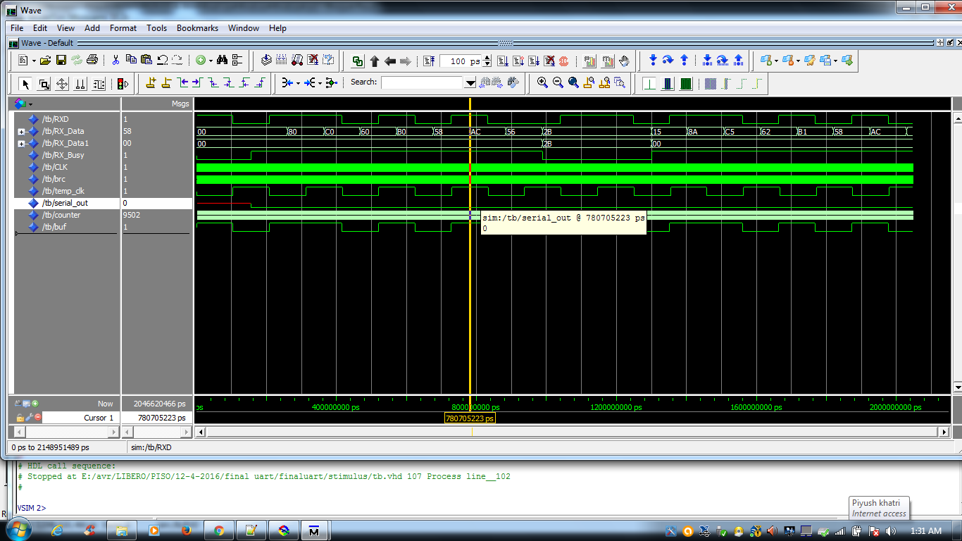
thanks for your reply. in many ways vhdl is confusing me.because i have used embedded c lot. but thanks for your support can you explain me ?? that in receiver part why you used 4 bit shift register (rxd_sr). Rushin T. wrote: > that in receiver part why you used 4 bit shift register (rxd_sr). Its due to what I wrote: Lothar M. wrote: >>> 3. always synchronize in external signals to that clock So the first 3 flipflops are for synching to the FPGA clock (although 2 would be enough). And the fourth one is for the edge detection of the start bit... hello can you help me in writing test bench?? See there at the very end for a simple stimuli testbench for a RS232 receiver: http://www.lothar-miller.de/s9y/archives/60-RS232-IO.html#extended thanks for your support. in your code RXD is input and in testbench , you are giving C3. dout is output and for sometime i get C3. now i want like when i transmit C3, in dout i can read C3. what is 3D,3F,3B So, it seems like its time to start thinking... With the simulator you can have a look for the internal signals of each module. There you can find the timing problems. Be sure: its your specific implementation that's faulty, because that RS232 interface from my HP runs fine in several designs all over the world. And to find your problem in your code you should post your implementation causing that problem... ok thanks have you ever used proasic FPGA??. i am using proasic A3E1500. for that i am using libero. in libero when i am doing presynthesis simulation for your code, it will give me result. but for post synthesis. i am not getting result. can you help me?? I'm sorry, I don't know that toolchain. But also I didn't need anything other than behavioral (= pre synthesis) simulation the last ten years... Do all you need is a behavioral simulation and constraints. Rushin T. wrote: > i am not getting result. WHAT do you expect? And WHAT do you get instead? hi in your code dout is 8 bit parallel output. is it required to convert it into serial??? this is code for 50 mhz crystal. if I change crystal then what is change in code?? Simply change this generic: Quarz_Taktfrequenz : integer := 50000000; -- Hertz That's the crystal frequency... hello thanks for your great support. can you give me test bench of http://www.lothar-miller.de/s9y/categories/42-RS232 this code ?? because in this link http://www.lothar-miller.de/s9y/archives/60-RS232-IO.html#extended in code there is no generic for changing clock frequency. hey thanks for your support. i don't require testbench now. i have made it. i fuse that code in my proasic fpga. but i am not getting result. i am transmitting 'J' from hyperterminal. i am trying to get that pattern on fpga i/o pin. but my problem is if i am not transmitting any thing some i/o pins are high. some are low. can you tell me?? how you test that code on hardware?? do you think that in code it require power on reset pin?? Rushin T. wrote: > in code there is no generic for changing clock frequency. That code is not good for use in a FPGA. It is designed for a CPLD. Take that with only 1 clock! Rushin T. wrote: > have made it. Obviously not... :-/ Rushin T. wrote: > how you test that code on hardware?? FIRST it had to run in simulation! THEN I simply implemented it on FPGA and did some tests with a terminal software. can you tell me which code is for cpld and which code is for fpga?? The code with only 1 clock in the whole design is for synchronous FPGA design. That there is it: http://www.lothar-miller.de/s9y/categories/42-RS232 But to repeat it once more: the simulator is the debugger for the behavioral model. And if the simulation is working and the "one and only crystal oscillator clock" is used throughout the whole design and every async input is synched to that "one and only crystal oscillator clock" then the design will run in reality also. thanks for your great support. today i made simple code. i am giving input to fpga from my rs232 port. and in my code i assign this input to my output when rising edge of clock arrives.i am using 48.86Mhz crystal. but at my output i am not getting data. when i gave clock to that pin, i am getting clock at output.. so i think problem occurs when i am trying to give input from fpga...! Rushin T. wrote: > today i made simple code. I don't know that code, so I cannot help you any further... If you post it as an attachment named *.vhdl I can setup a testbench (that's only a few minutes) and tell you what's going wrong. As already said several times: You MUST run a simulation! Its very easy here! hello thanks.your code helps me lot. now it is running on hardware. when i am transmitting serial input from pc , i am getting output on fpga i/o pins. now my output is parallel. but i want to convert it into serial. i am trying it. i have written second process for it can you help me?? hey there my output is RXDATA1, from screenshot, you can see that it is 2B which is parallel. now i want to convert into serial at 9600 hz. can you help me?? i have also uploaded my code and test bench here
Attached files:
waiting for your reply Reply |