i want to convert 8 bit serial data into 8 bit parallel data my code is
here
library IEEE;
use IEEE.STD_LOGIC_1164.all;
entity PAR2SER is
port(
din : in STD_LOGIC;
clk : in STD_LOGIC;
reset : in STD_LOGIC;
dout : out STD_LOGIC_VECTOR(7 downto 0)
);
end PAR2SER;
architecture sipo_behavior_arc of PAR2SER is
begin
sipo : process (clk,din,reset) is
variable s : std_logic_vector(7 downto 0) := "00000000" ;
begin
if (reset='1') then
s := "00000000";
elsif (rising_edge (clk)) then
s := (din & s(7 downto 1));
end if;
dout <= s;
end process sipo;
end sipo_behavior_arc ;
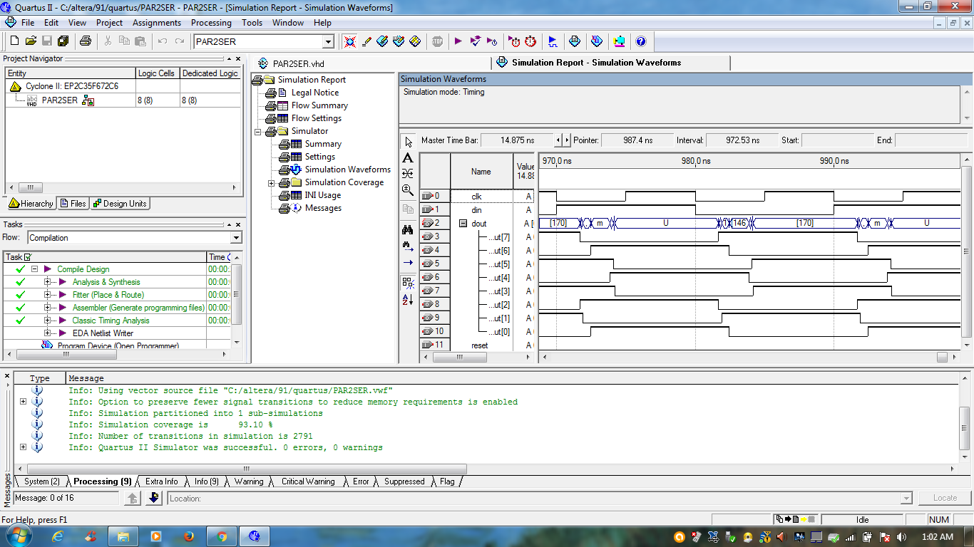
but i am not getting correct data. here image is i have uploaded
Attached files:
-

stop.png
150 KB
is this the behavioral simulation or the simulation of the netlist? how
about posting the testbench? the waveforms looking strange
the waveform looks somewhat strange cause the simulation includes
timing: the individual bits of dout switch with some delay with respect
to the positive CLK-edge (~6ns .. 8ns). If one takes this delay in
consideration and looks at dout only at the "next" rsising CLK-edge,
then dout toggles between xAA and x55 - just as it should when din
toggles with every CLK-cycle.

One thing I do not understand is, that dout as std_logic_vector is
displayed as "uninitialized" every other CLK-cycle - though each
individual bit of the std_logic_vector is showing a well defined logic
value. Besides that the simu just shows, what one should expect from the
given description.

(By the way: Ser2Par would be a much more appropriate name for this
component than Par2Ser)
Rushin thakkar wrote:
> but i am not getting correct data.
For me the wavrform looks fine: in the shift register is "01010101" or
"10101010" at the rising edge of clk. What could you expect instead?

BTW: do a behavioural simulation instead of this post route timing
simulation. It makes things much easier and more obvious...

Achim S. wrote:
> One thing I do not understand is, that dout as std_logic_vector is
> displayed as "uninitialized" every other CLK-cycle - though each
> individual bit of the std_logic_vector is showing a well defined logic
> value.
That looks really kind of strange...
Achim S. wrote:
> One thing I do not understand is, that dout as std_logic_vector is
> displayed as "uninitialized" every other CLK-cycle - though each
> individual bit of the std_logic_vector is showing a well defined logic
> value. Besides that the simu just shows, what one should expect from the
> given description.

I assume that this is kind of enumerated display of the value. "U" the
corresponds to x"55", "m" to x"6D". Values x"80" and above are shown as
is...
oh man, you're right: dout is displayed as ASCII-Character, and
non-printable chars are schown as decimal numbers. A strange setting,
but then every aspect of the simulation does show the expected result.
Please log in before posting. Registration is free and takes only a minute.
Existing account
Do you have a Google/GoogleMail account? No registration required!
Log in with Google account
Log in with Google account
No account? Register here.