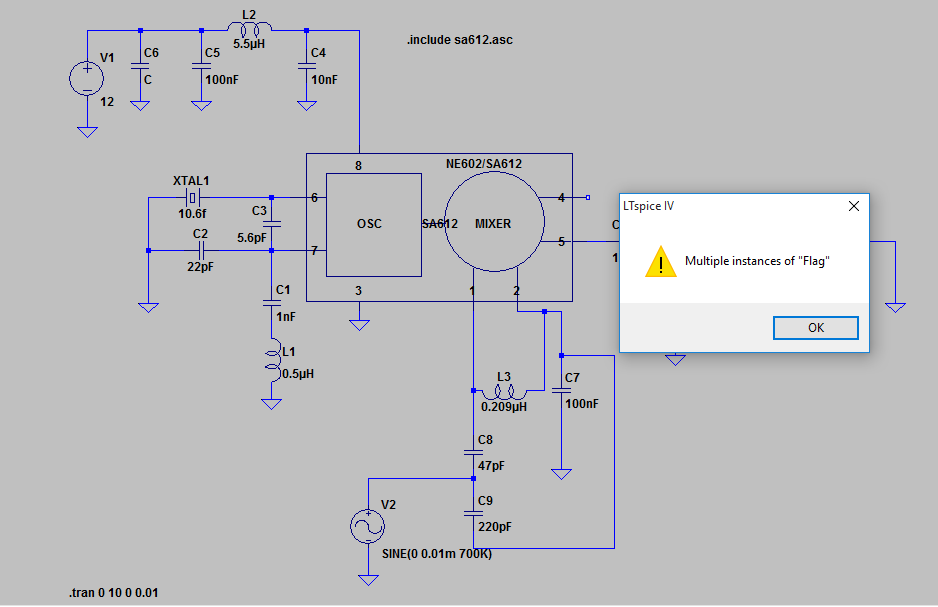
Hi,

I am trying to develop an RF circuit, but quite inexperienced with
LTSpice. As much as I check out on Google, I could not find a solution
to my problem, where the Run command for Transient analysis returns
"Multiple Instances of Flag" error. I examined the model file with a
text editor, but it was no use, I could not find a specific error.

It is probably because of my mistake that the model I use is not well
connected by its model files to the schematic. The model I used for
SA612 mixer and an ss is attached.

Anyone knows how can I get rid of this "Multiple Instances of Flag"
error?
Attached files:
-

flag_1.PNG
20 KB
Hierarchical schematics didn't need the ".include" command.

Changing this line into a comment (and assigning a value to C6) the
simulation runs without error messages using the automatically generated
symbol.

If you encounter further errors, please attach your "SA612.asy" too.
Hi,
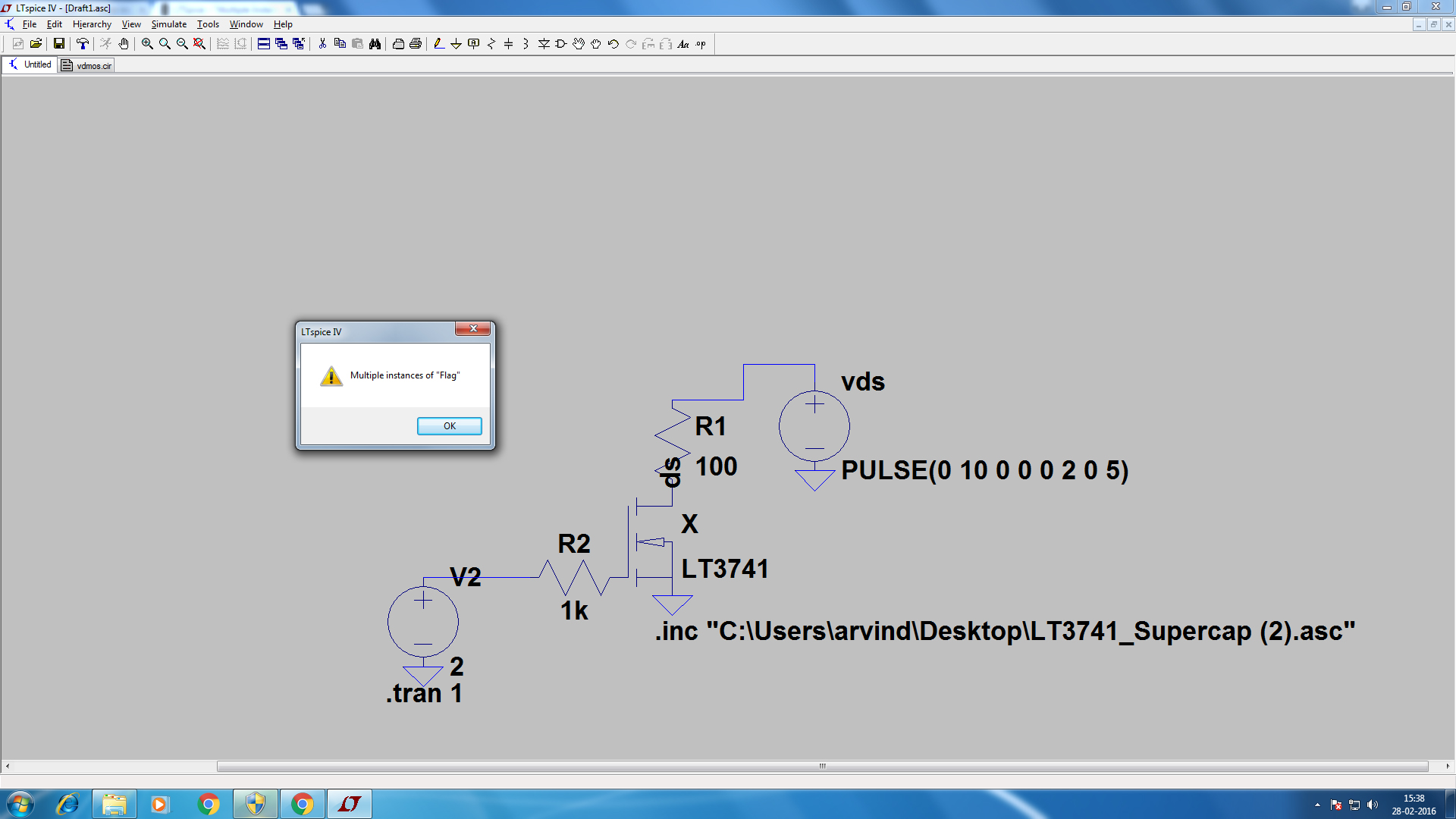
Iam trying to include the file LT3471 it end up showing multiple
Instance of flag error. Help me to fix this error.
Thank you!
Attached files:
-

LT3741VDMOS.jpg
450 KB
Hi,

I am trying to include the file LT3471 it end up showing multiple
Instance of flag error. Help me to fix this error.

                          Thank you!
Why do you try to include a schematic? That's not possible. Copy the
schematic into this schematic or make a hierarchical schematic.
Here are two diode data sheets. I want to focus on modeling SER30KE60
because it has a lot of data.  The second data sheet provides
definitions of typical reverse recovery parameters.


Tasks:


1. Write a .meas statement in diode test schematic that will find the
diode peak reverse current.


2. Run a .meas script from the waveform viewer. Create a text file that
has the same .meas statement and give it the ending .meas  The results
are in the .log file


3. Run a .meas script from CMD.


4. Use Python to run a simulation, run .meas, and capture the peak
reverse current from the log file.


the question is how to do this from datasheet without modeling a circuit
cephas wrote:
> the question is how to do this from datasheet without modeling a circuit
Pls start a new thread for a totally new question!