I am making a circuit with IGBT for charging a capacitor. The Driver
which i use is a high side driver as suggested by Infineon.I have
received working spice model of the driver from Infineon for my
application. however the simulation in LT spice is not giving required
output and also it is very slow. i am attaching the simulation file.
Kindly guide me in finding the error.

Regards

Sriniketh
sriniketh schrieb:
> i am attaching the simulation file.
Two things:
1. you have posted in the German forum. Post English questions in the
embdev.net forum please.

2. for the users with tablets and phones: attach a screenshot of your
schematic. Then they also can try to help you....
Attached files:
-

highmos.jpg
250 KB -

highigbt.jpg
260 KB
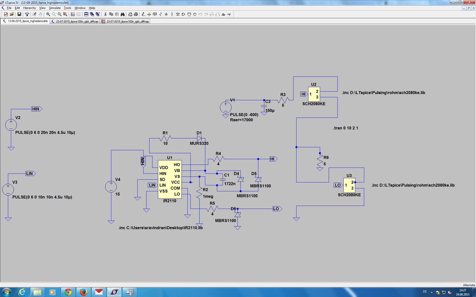
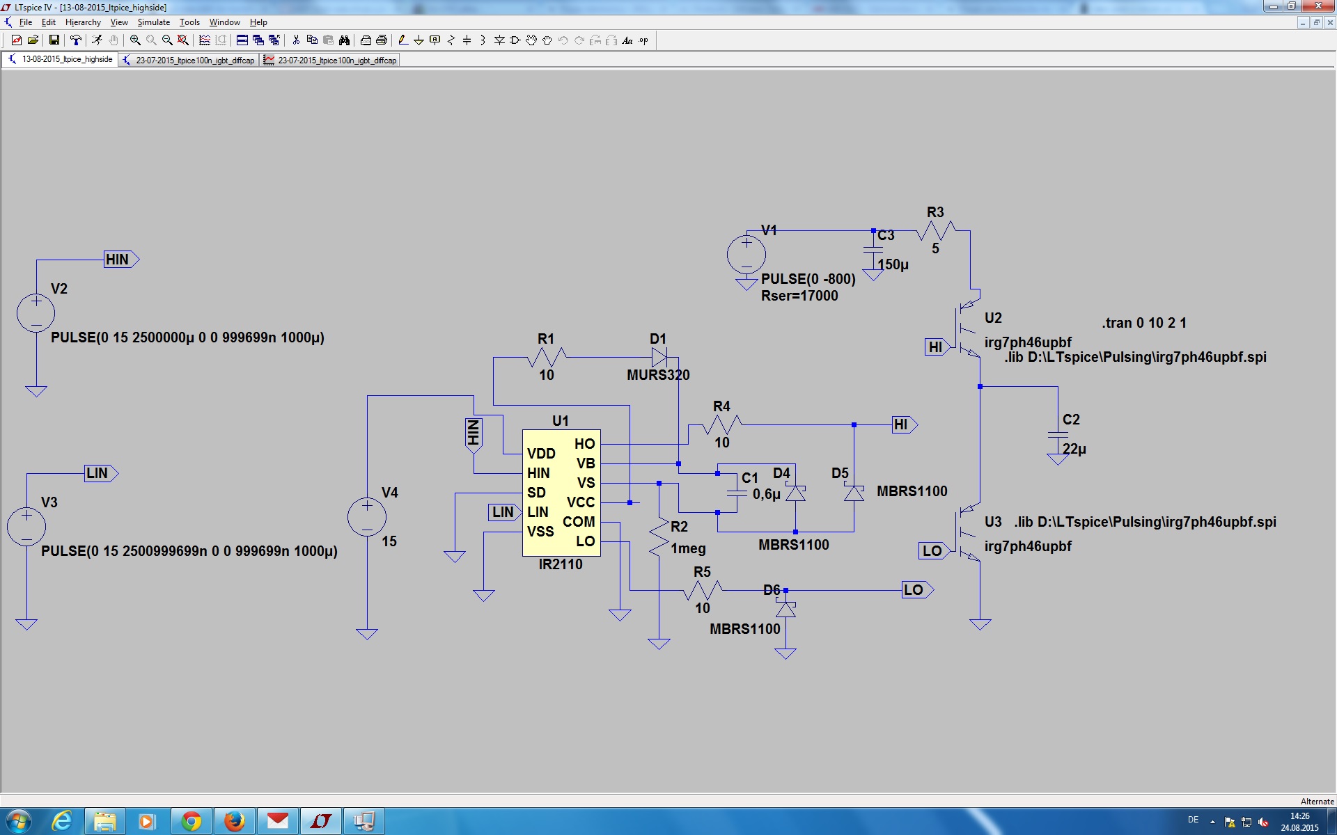
I am making a circuit with IGBT for charging a capacitor. The Driver
which i use is a high side driver as suggested by Infineon.I have
received working spice model of the driver from Infineon for my
application. however the simulation in LT spice is not giving required
output and also it is very slow.I have also tried the same concept with
power MOSFETs. i am attaching the simulation file.
Kindly guide me in finding the error.

Regards

Sriniketh
sriniketh wrote:
> I will post in the other website
I already shifted your thread to embdev.net (see the URL line of your
browser).
VS of the IR2110 is wrongly connected. Note that it should connect to
the load output between Hi- and Lowside, according to the datasheet.
D4 is unnecessary as is R1 and R2.
Attached files:
-

circuit.jpg
240 KB

Now i would like to drive the circuit with negative 800VDC . I have
doubts regarding the reference ground for the control section and the
power section.In the control section i can use the ground of 0V. and for
the power section i have -800VDC. Do i need to modify my circuit for my
negative power source . kindly guide
No, this will blow up the Lowside MOSFet immediately, as it will see
800V between Source and Gate. Possibly the only way to solve this is to
reference the complete PA including the driver IC to the -800V and drive
the circuit with optocouplers.
The next problem ist to generate the 12V-15V for the driver and charging
pump, with about -785V.
Matthias Sch. wrote:
> No, this will blow up the Lowside MOSFet immediately, as it will
> see
> 800V between Source and Gate. Possibly the only way to solve this is to
> reference the complete PA including the driver IC to the -800V and drive
> the circuit with optocouplers.
> The next problem ist to generate the 12V-15V for the driver and charging
> pump, with about -785V.

Thank you for the information.

I have tried the bootstrap example for high side driving. Can i connect
the load to the collector side and drive it as low side driver ?. Is it
possible ?.Can you suggest sample circuit for solving such a condition

Is just the bootstrap capacitor is not enough to drive the gate? Do i
also need charge pump circuit ?

Thanks in Advance

Sriniketh
Please log in before posting. Registration is free and takes only a minute.
Existing account
Do you have a Google/GoogleMail account? No registration required!
Log in with Google account
Log in with Google account
No account? Register here.