Dear friends...
I need to implement these two filters which are attached .
or you can find them here:
http://0up.ir/do.php?imgf=DSC-0594_f878b.jpg

how can i implement these delays... plzzzzzzzzzzzz help me
Attached files:
-

DSC_0594.jpg
180 KB
you have to save your data for one cycle time.

an example: (call this function ever cycle)

int delay_register(int inputdata)
{
 static int delay_register = 0;

 output = delay_register;

delay_register = inputdata;

retrun output;
}
sorry, this was in the programming language c, but vhdl works nearly in
the same way ;)
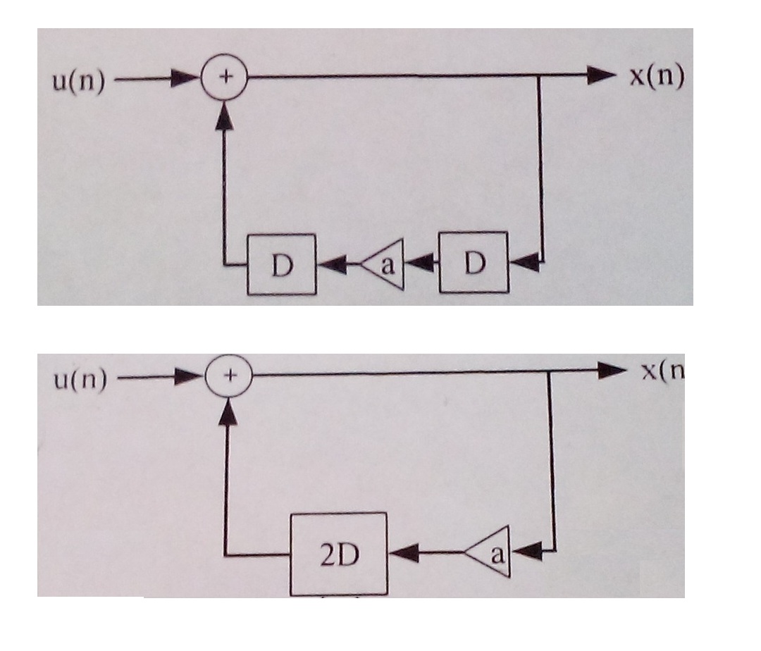
What explanation do you need?

Like you posted, the filter is described by x(n)=ax(n-2)+u(n), where
x(n) is the output signal at time n and u(n) is the input at n.
D and 2D delay the inputsignal by 1 or 2 clocks, respectively.

In VHDL, the delays are registers.

I don't think that anybody here wants to do your homework.
http://wolframalpha.com/input/?i=transfer+function+1%2F%281+-+a*z%5E-2%29&x=0&y=0

Replace the 2 with your value for a.
thanks for your comments!!!!!!! But be sure that I have tried to do it
my self!!!!!!!!
if some body knows that how this problem is solved just can help
kindly!!!!!!!!!!!
H have thought about it vary much! I just want to get sure about it! :/
This is my code:
______________________________________________________________

library IEEE;
use IEEE.STD_LOGIC_1164.ALL;
use IEEE.STD_LOGIC_arith.all;
use IEEE.STD_LOGIC_SIGNED.all;


entity filter_fir1 is
    Port ( u : in  STD_LOGIC_VECTOR(5 DOWNTO 0);
           a : in  STD_LOGIC_VECTOR(2 DOWNTO 0);
        clk: in STD_LOGIC; rst: in STD_LOGIC;
        x : buffer  STD_LOGIC_VECTOR(7 DOWNTO 0));
end filter_fir1;

architecture Behavioral of filter_fir1 is
signal s1: std_logic_VECTOR(10 downto 0);
signal s2: std_logic_vector(7 downto 0);
begin

process(clk)
begin
  if rst='1' then
    s2<="00000000";
  elsif rising_edge(clk) then
    s1<=a*x;
    s2<=s1(7 downto 0);
  end if;
end process;
x<=s2+u;
end Behavioral;

________________________________________________________________

I don't know how to impelment delays!!!!!!!!!!!!!!!!!!
when 2 dleays are  applied and when one delay is applied , then
multiplication and then another delay!!!!!!!!!!!!!!!!!!!!
just answer if you wannna help!!!!!!!!!!!!!!!!!!!!!!!!!!
> just answer if you wannna help!!!!!!!!!!!!!!!!!!!!!!!!!!


Just use even more !!!!!!!!!!!!!!!!!!!!!!
and scream out loud and add more
plzzzzz hlp
then maybe a lone superhero will come by and do your homework.
It doesn't look that bad.

rst is missing in the sensitivity list.
I personally wouldn't use an asynchronous reset, but I guess this is how
it was explained in your lecture.
You should also reset s1, because otherwise the reset is pretty much
pointless.

Regarding the delays: As I said earlier, these are implemented as
registers. In your case, s1 and s2 are exactly those registers. They get
their value on every rising edge of clk, contrary to x, which always
outputs s2+u, independent of the cock.

Your implementation is the second design in the picture you posted.
If you want do implement the first, you first assign x to s1 and then
s1*a to the s2, again with some scaling.

What exactly is not working?
gg wrote:
>> just answer if you wannna help!!!!!!!!!!!!!!!!!!!!!!!!!!
>
>
> Just use even more !!!!!!!!!!!!!!!!!!!!!!
> and scream out loud and add more
> plzzzzz hlp
> then maybe a lone superhero will come by and do your homework.

is it a problem people help each other!!!!!!!!
I am sorry for you
Alexander F. wrote:
> It doesn't look that bad.
>
> rst is missing in the sensitivity list.
> I personally wouldn't use an asynchronous reset, but I guess this is how
> it was explained in your lecture.
> You should also reset s1, because otherwise the reset is pretty much
> pointless.
>
> Regarding the delays: As I said earlier, these are implemented as
> registers. In your case, s1 and s2 are exactly those registers. They get
> their value on every rising edge of clk, contrary to x, which always
> outputs s2+u, independent of the cock.
>
> Your implementation is the second design in the picture you posted.
> If you want do implement the first, you first assign x to s1 and then
> s1*a to the s2, again with some scaling.
>
> What exactly is not working?

I am really thankful for your answer.....
I am a new learner that is why my question was easy for others.

Regards....
Please log in before posting. Registration is free and takes only a minute.
Existing account
Do you have a Google/GoogleMail account? No registration required!
Log in with Google account
Log in with Google account
No account? Register here.