Hello

I am implementing Ring Oscillator with feedback using
nand and also with not gate in VHDL,and not getting expected
output, need some inputs. Code as follows:-
Nand gate:
1
entityosc2is
2
Port(a:inoutSTD_LOGIC;
3
b:inoutSTD_LOGIC);
4
endosc2;
5
6
architectureBehavioralofosc2is
7
signalx1,x2,x3,x4,x5:STD_LOGIC;
8
9
componentnandGateis
10
Port(inp1:inSTD_LOGIC;
11
inp2:inSTD_LOGIC;
12
out1:outSTD_LOGIC);
13
endcomponent;
14
15
begin
16
-- a <= b;
17
18
l0:nandGateportmap(inp1=>a,inp2=>a,out1=>x1);
19
l1:nandGateportmap(inp1=>x1,inp2=>x1,out1=>x2);
20
l2:nandGateportmap(inp1=>x2,inp2=>x2,out1=>b);
21
22
endBehavioral;
Not Gate:
1
entityoscis
2
Port(inp:inoutSTD_LOGIC;
3
oup:inoutSTD_LOGIC);
4
endosc;
5
6
architectureBehavioralofoscis
7
signalx1,x2,x3,x4:STD_LOGIC;
8
9
componentandgateis
10
Port(inp1:inSTD_LOGIC;
11
inp2:inSTD_LOGIC;
12
out1:outSTD_LOGIC);
13
endcomponent;
14
15
componentinverter1is
16
Port(a:inSTD_LOGIC;
17
b:outSTD_LOGIC);
18
endcomponent;
19
20
begin
21
-- x4 <= oup;
22
23
l0:andgateportmap(inp1=>inp,inp2=>oup,out1=>x1);
24
l1:inverter1portmap(a=>x1,b=>x2);
25
l2:inverter1portmap(a=>x2,b=>x3);
26
l3:inverter1portmap(a=>x3,b=>oup);
27
28
endBehavioral;
i am not getting any input. How to give feedback (ie output to input) so
ring oscillator will be toggle. thanks
If i were your teacher, you would get the worst grade just for this port
definition! Why the heck is an input connected to an inout port? And why
an output even so? Summary: laziness ist not good for good grades!
Katta Satish wrote:> and not getting expected output
What do you get instead? And how do you see the erroneuos result?
> How to give feedback (ie output to input)
You use a signal to connect them together. And you do that already with
the x1..x3 signals. Just finisch up the job by using the x4 signal:
1
entityoscis
2
Port(inp:inSTD_LOGIC;
3
oup:outSTD_LOGIC);
4
endosc;
5
6
architectureBehavioralofoscis
7
signalx1,x2,x3,x4:STD_LOGIC;
8
9
componentandgateis
10
Port(inp1:inSTD_LOGIC;
11
inp2:inSTD_LOGIC;
12
out1:outSTD_LOGIC);
13
endcomponent;
14
15
componentinverter1is
16
Port(a:inSTD_LOGIC;
17
b:outSTD_LOGIC);
18
endcomponent;
19
20
begin
21
oup<=x4;
22
23
l0:andgateportmap(inp1=>inp,inp2=>x4,out1=>x1);
24
l1:inverter1portmap(a=>x1,b=>x2);
25
l2:inverter1portmap(a=>x2,b=>x3);
26
l3:inverter1portmap(a=>x3,b=>x4);
27
28
endBehavioral;
Why do you instantiate each lousy gate manually? An AND gate you can
write down this way:
result <= a and b;
And a NOT gate is simply this:
result <= not a;
So finally your description looks like that:
Dear Miller,

Thanks for correcting me.
In my test bench, when i gave as below commenting clk signals , for
single
value there is no toggle for 2 inverter gate.
1
waitfor10ns;
2
reset<='0';
3
wait;-- i want without commenting this, else input is toggling the same
4
soouputtoggles.
But a ring osc with any feedback should toggle with any input.
I am trying to check delay in Ring Osc when odd inverters.
Katta Satish wrote:> In my test bench
What simulation do you perform? A behavioural simulation or a post P&R
(timing) simulation?
You cannot simulate this design without timing information. A simple
behavioural simulation will give rubbish or an error due to the
combinational loop...
One more hint: don't insert a "testbench" nor a "bench" inside the tag
[vhdl testbench]
---
[/vhdl bench]
Simply use it as i posted it previously and as its stated a few lines
above the edit box...
Sir,

Thanks.
I am using Xilinx ISE 12.4. and use ISE simulator.
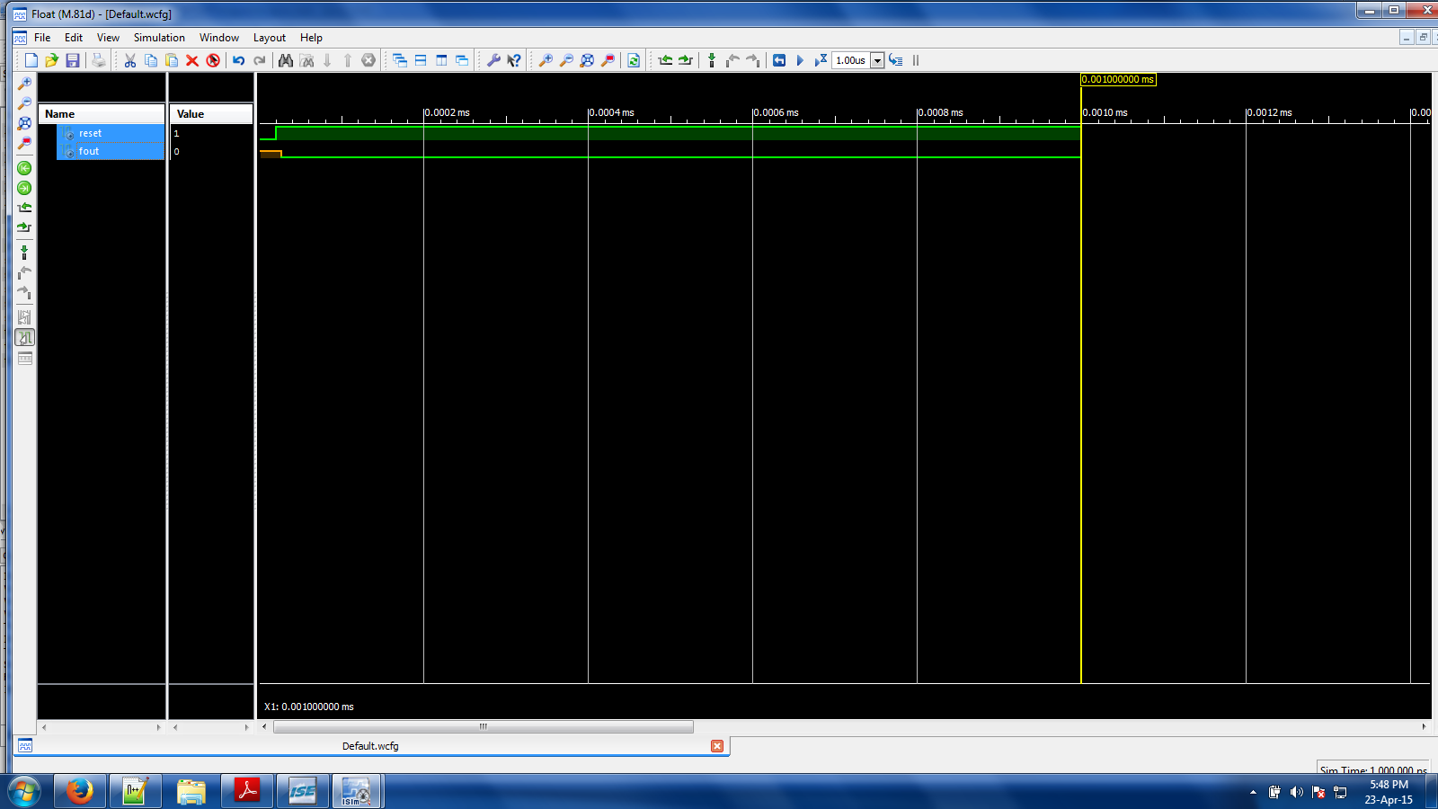
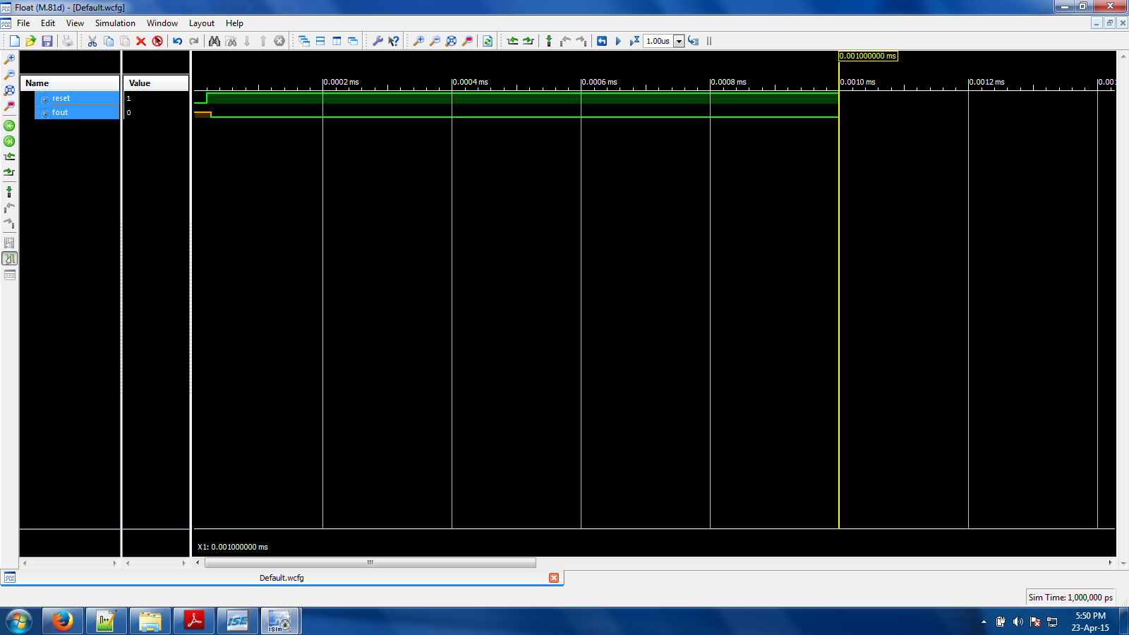
Attached jpg file of PlaceRoute and Simulate Behavioral Model as per
previous test bench input.

No Toggling of Ring Osc.
Is do file generates for ISE Simulator?
Refering to https://www.youtube.com/watch?v=DgRrATFd3jc the author uses
do
file for model sim.

Regards
As I said: you cannot do a behavioral simulation on a combinatorial
loop. Didn't you read what I wrote?

What's the code for the waveform above? And what about the other
internal signals values?
Sir,

Thanks for your time.
1) Q: you cannot do a behavioral simulation on a combinatorial
loop ?
A : As in my first post i wrote without loops.where i tried to
give feedback.

2)Q: What's the code for the waveform above? --
A: Synthesis code
:http://www.lothar-miller.de/s9y/categories/29-Ringoszillator.

3) Q : what about the other internal signals values?
   A : Gave ring <= "011" in the testbench.
   Errors:"F:/FPGAP/ringosc/osc3_tb.vhd" Line 84: <ring> is not
declared.
   ERROR:HDLCompiler:854 - "F:/FPGAP/ringosc/osc3_tb.vhd" Line 38: Unit
   <behavior> ignored due to previous errors.
   VHDL file F:/FPGAP/ringosc/osc3_tb.vhd ignored due to errors

3) Do i need to give values to signals also?
   Gave values to rst only. such as ring <= "011" in the testbench.
   NEVER read giving values to signal.

Regards
Katta Satish wrote:> 2)Q: What's the code for the waveform above? --> A: Synthesis code> :http://www.lothar-miller.de/s9y/categories/29-Ringoszillator.
Did you have a little look at the waveform pictures there and at yours?
My ring oscillator is reset when reset='1'. So in your waveform the ring
oscillator is always in reset!
> 3) Q : what about the other internal signals values?> A : Gave ring <= "011" in the testbench.
Of course thats not possible, because in the VHDL module named
"testbench" the signal "ring" is unknown. But you can look inside the
component under test with the simulator. Just open the corresponding
node of the component tree and add the desired signal to the wavefrom.
Could you give my une impression, in how it was possible to simultate
these VHDL physique correctely?  Normallely it is not possible to
simulate phyisquel signals and wirings. For other reason it was of
interrest when you use these ciruits in gerneal? Where is the use of an
oscillation without a realation?