EmbDev.net

Forum: FPGA, VHDL & Verilog State Machine for SPI Master/Slave Interface


von Nayan P. (nay)


Attached files:

Rate this post
useful
not useful
Dear all,

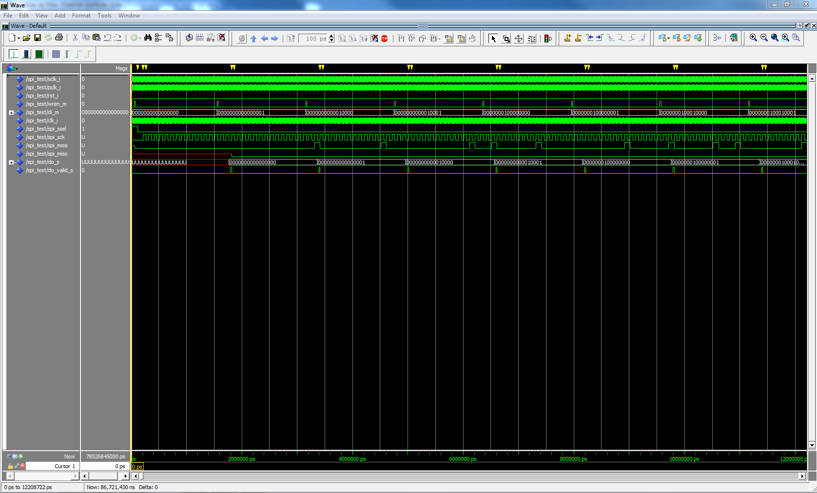
I am trying to write a state machine that checks to see if correct data 
is being received on the SPI link by lighting an LED.

I have written a code but I am not sure if I am writing the state 
machine correctly, it definitely does not compile.

Here is the code that I have written in relation to the test bench, 
please find the file attached.

1
library IEEE; -- Reference for VHDL source code  
2
use IEEE.STD_LOGIC_1164.all; -- Package defined in the IEEE (Found in library IEEE)
3
4
-- Entity declaration
5
entity spi_statemachine is
6
   generic (n: positive := 16; -- Number of bits
7
  port (-- Master --                        
8
      di_m: in std_logic_vector(15 downto 0);
9
      wren_m: in std_logic;
10
      -- Slave --
11
      do_s: out std_logic_vector(15 downto 0);
12
      do_valid_s: out std_logic;
13
      -- Clock operation --
14
      rst_i: in std_logic;
15
      clk_i: in std_logic;
16
      -- Output detection --
17
      correct: out std_logic);
18
end spi_statemachine;
19
20
-- Architecture behaviour
21
architecture detect of spi_statemachine is
22
type state_type is (createData, writeData, delay, writeEnable,
23
              checkValid, receivedData, checkFinished);  -- Enumeration type
24
signal state: state_type;
25
begin
26
  P1: process (clk_i, rst_i) -- Clock and reset
27
  variable dataLength: integer := n; -- Length of data
28
  variable count: integer := 1;
29
  begin
30
    if rst_i = '0' then -- Reset operation used initialize all signals to predetermined state
31
      state <= createData; 
32
    elsif clk_i'event and clk_i = '1' then  -- Signal attribute used to test for a change on a signal
33
      case state is
34
        when createData =>
35
            state <= writeData;
36
          else
37
            state <= createData;
38
          end if;
39
40
        when writeData =>
41
            di_m <= std_logic_vector(to_unsigned(dataLength,n)); -- Write data
42
            state <= delay;
43
          
44
        when delay =>
45
            count := count + 1;
46
          if (count > 1) then
47
            state <= writeEnable;
48
          count := 0;
49
          else
50
            state <= delay;
51
          end if;
52
        
53
        when writeEnable =>
54
          wren_m <= '1';
55
          state <= checkValid;
56
          
57
        when checkValid =>
58
          wren_m <= '0';
59
          state <= receivedData;
60
        
61
        when receivedData =>
62
          if do_s = di_m then
63
            state <= checkFinished;
64
          end if;
65
        
66
        when checkFinished =>
67
          correct <= '1';
68
        when others => null;
69
      end case;
70
    end if;
71
  end process;
72
end detect;

Any kind of help will be appreciated.

Kind regards,

Nay

von ruusel (Guest)


Rate this post
useful
not useful
Hi nayan,
you have a lot of mistakes in your syntax. Check your brackets and be 
sure that every if has its else end endif aso...

von Nayan P. (nay)


Rate this post
useful
not useful
ruusel wrote:
> Hi nayan,
> you have a lot of mistakes in your syntax. Check your brackets and be
> sure that every if has its else end endif aso...

Thank you for the reply.

How do I declare an output from the slave component to the code that I 
am writing above?

Kind regards,

Nayan

von Lothar M. (Company: Titel) (lkmiller) (Moderator)


Rate this post
useful
not useful
Nayan Patel wrote:
> How do I declare an output from the slave component to the code that I
> am writing above?
What slave?

> it definitely does not compile.
But you get no warnings or error messages?

> Here is the code that I have written in relation to the test bench
So the waveform picture is what your code should do after being 
completed? Where's the testbench for that waveform?

von Nayan P. (nay)


Attached files:

Rate this post
useful
not useful
Lothar Miller wrote:
> Nayan Patel wrote:
>> How do I declare an output from the slave component to the code that I
>> am writing above?
> What slave?
>
>> it definitely does not compile.
> But you get no warnings or error messages?
>
>> Here is the code that I have written in relation to the test bench
> So the waveform picture is what your code should do after being
> completed? Where's the testbench for that waveform?

I am using a master block to send data to the slave block and the state 
machine block will check to see if the correct data is received.

I get the following error message:
1
Error (10482): VHDL error at spi_statemachine.vhd(70): object "do_o" is used but not declared

I am trying to assign the output 'do_o' of the slave block to the input 
'di_m' of my state machine block.

Please find the file of the test bench attached.

Kind regards,

Nayan

von Lothar M. (Company: Titel) (lkmiller) (Moderator)


Rate this post
useful
not useful
Nayan Patel wrote:
> Please find the file of the test bench attached.
This here could be cut down several lines:
1
-- Clock generator (50% duty cycle)
2
  -- Master clock --
3
  -- Serial clock --
4
  clk_process_serial: process        -- Identifying the process
5
  begin                        -- Begin process
6
       sclk_i <= '0';              -- Serial clock signal is '0'.
7
       wait for clk_period/2;          -- Serial clock signal is '0' for 5ns
8
       sclk_i <= '1';              -- Serial click signal is '1'
9
       wait for clk_period/2;          -- Serial clock signal is '1' after 10ns
10
  end process clk_process_serial;      -- End process
11
  
12
  -- Parallel clock --
13
  clk_process_parallel: process        -- Identifying the process
14
  begin                        -- Begin process
15
       pclk_i <= '0';              -- Slave clock signal is '0'.
16
       wait for clk_period/2;          -- Slave clock signal is '0' for 5ns
17
       pclk_i <= '1';              -- Slave clock signal is '1'
18
       wait for clk_period/2;          -- Slave clock signal is '1' after 10ns
19
  end process clk_process_parallel;    -- End process
20
  
21
  -- Slave clock --
22
    clk_process_slave: process        -- Identifying the process
23
  begin                        -- Begin process
24
       clk_i <= '0';                -- Slave clock signal is '0'.
25
       wait for clk_period/2;          -- Slave clock signal is '0' for 5ns
26
       clk_i <= '1';                -- Slave clock signal is '1'
27
       wait for clk_period/2;          -- Slave clock signal is '1' after 10ns
28
  end process clk_process_slave;      -- End process
Just by this here:
1
-- Clock generator (50% duty cycle)
2
  clk_i  <= not clk_i after clk_period/2; 
3
  sclk_i <= clk_i;
4
  pclk_i <= clk_i;

Nayan Patel wrote:
> I get the following error message:
I cannot find do_o in any of the VHDL code you provided. Is it hidden 
somewhere else?

And of course, this here won't work at all:
1
      :
2
      do_s: out std_logic_vector(15 downto 0);
3
      :
4
      :
5
          if do_s = di_m then    -- it is not allowed to read an output port!
6
      :
In VHDL a output cannot be read.

von Nayan P. (nay)


Attached files:

Rate this post
useful
not useful
Lothar Miller wrote:
> Nayan Patel wrote:
>> I get the following error message:
> I cannot find do_o in any of the VHDL code you provided. Is it hidden
> somewhere else?

The output 'do_o' is read from the slave block, please find the file of 
the master block and slave block attached.

Kind regards,

Nayan

von Lothar M. (Company: Titel) (lkmiller) (Moderator)


Rate this post
useful
not useful
And where is the file with the line of code causing the errror:
spi_statemachine.vhd(70)

Heck, it is so exhausting to worm every small bit of information out of 
someone...  :-/

von Nayan P. (nay)


Rate this post
useful
not useful
Lothar Miller wrote:
> And where is the file with the line of code causing the errror:
> spi_statemachine.vhd(70)
>
> Heck, it is so exhausting to worm every small bit of information out of
> someone...  :-/

Apologies for the confusion, please find state machine file attached.

I have also attached the wrapper (Top-level entity) for the 'spi_master' 
and 'spi_slave' cores, to synthesize the 2 cores and test them in the 
simulator.

Kind regards,

Nayan

Please log in before posting. Registration is free and takes only a minute.
Existing account
Do you have a Google/GoogleMail account? No registration required!
Log in with Google account
No account? Register here.