SPI Master/Slave Interface

OP #3967053
Rate this post
useful
not useful
Dear All,

I am trying to simulate the testbench of the master and slave SPI 
interfaces from the opencores.org website but I get the following error 
message:

1
Error (10533): VHDL Wait Statement error at spi_loopback_test.vhd(209): Wait Statement must contain condition clause with UNTIL keyword

I am using Quartus for the VHDL files and Modelsim to view the testbench 
results. Also, I have set the "spi_loopback_testbench.vhd" file as the 
"Top-Level Entity".

I will appreciate it if anyone can help me figure out how to solve the 
error. Please find the files attached.

Thank you.

Kind regards,

Nay
Moderator (Company: Titel) #3967385
Rate this post
useful
not useful
Nayan Patel wrote:
> but I get the following error message:
You cannot synthesize a testbench on hardware. You can use a testbench 
only for simulation!

Some hints:
1.
1
use ieee.numeric_std.all;
2
use ieee.std_logic_unsigned.all;
Using both of them together is not a good idea, because then you get 
some type definitions doubled...

2.
1
integer range SPI_2X_CLK_DIV-1 downto 0;
A integer usually is defined with a ascending range...

3.
1
        if spi_ssel_i = '1' then                                -- async clr
NEVER EVER use an async input directly in a FSM. Let me repeat it once 
more: NEVER!!! If you don't sync in the external signel this will happen 
sooner or later, now or then:
http://www.lothar-miller.de/s9y/archives/64-State-Machine-mit-asynchronem-Eingang.html
(its German, try Google translator)
OP #3969059
Rate this post
useful
not useful
Lothar Miller wrote:
> Nayan Patel wrote:
>> but I get the following error message:
> You cannot synthesize a testbench on hardware. You can use a testbench
> only for simulation!
>
> Some hints:
> 1.
1
> use ieee.numeric_std.all;
2
> use ieee.std_logic_unsigned.all;
3
>
> Using both of them together is not a good idea, because then you get
> some type definitions doubled...
>
> 2.
1
> integer range SPI_2X_CLK_DIV-1 downto 0;
2
>
> A integer usually is defined with a ascending range...
>
> 3.
1
>         if spi_ssel_i = '1' then                                -- async 
2
> clr
3
>
> NEVER EVER use an async input directly in a FSM. Let me repeat it once
> more: NEVER!!! If you don't sync in the external signel this will happen
> sooner or later, now or then:
> 
http://www.lothar-miller.de/s9y/archives/64-State-Machine-mit-asynchronem-Eingang.html
> (its German, try Google translator)

I just figured out that the "spi_loopback.vhd" file is meant to be set 
as the "Top-Level Entity".

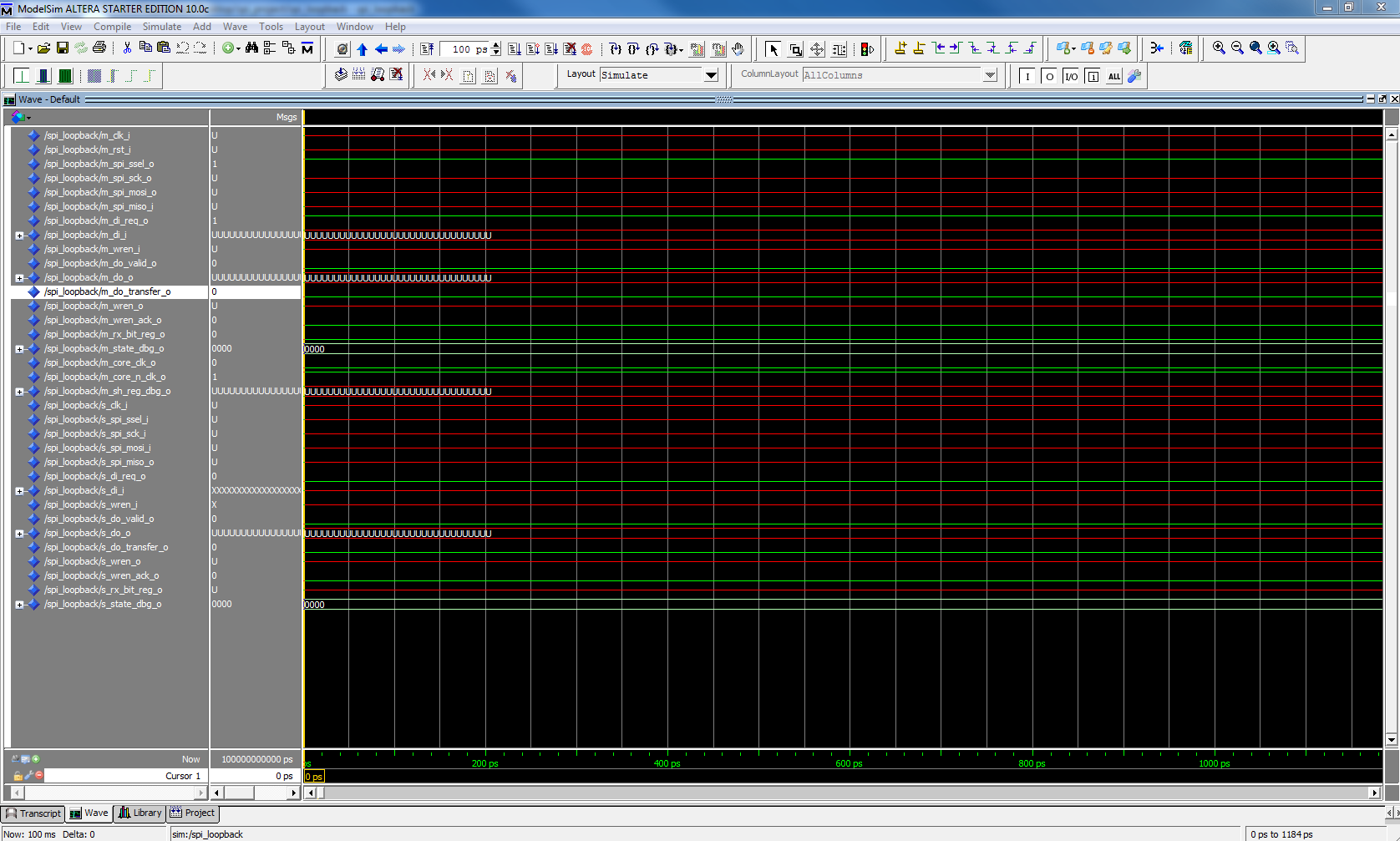
I simulated the "spi_loopback.vhd" file but I get the following errors 
as shown in the file attached. I am not sure why I am getting these 
errors.

Nay
Attached files:
Moderator (Company: Titel) #3969147
Rate this post
useful
not useful
Nayan Patel wrote:
> I get the following errors as shown in the file attached.
I can see no error there. Just some red and green lines.

And I see a time scale up to some 1200ps. But your test bench does its 
first action 3800ps later. Then its time for the first rising edge of 
the clock. And the reset will be set and released decades later...
OP #3969786
Rate this post
useful
not useful
Lothar Miller wrote:
> Nayan Patel wrote:
>> I get the following errors as shown in the file attached.
> I can see no error there. Just some red and green lines.
>
> And I see a time scale up to some 1200ps. But your test bench does its
> first action 3800ps later. Then its time for the first rising edge of
> the clock. And the reset will be set and released decades later...

Do you think I should change the time scale to see the inputs and 
outputs changing logics?
Moderator (Company: Titel) #3995557
Rate this post
useful
not useful
Did you simulate the design successfully? Does it do what you expect?

Then its time to go on real hardware. Just connect a SPI master and a 
SPI slave together and send data from a DIP switch continuously from the 
master to the slave. At the slave you connect your LED to the output. 
When you get the same LED on and off like you switch the DIP switches, 
then you have proven the MOSI direction.
For the MISO direction you can figure out easily a very similar test 
strategy...
OP #3995922
Rate this post
useful
not useful
Lothar Miller wrote:
> Did you simulate the design successfully? Does it do what you expect?
>
> Then its time to go on real hardware. Just connect a SPI master and a
> SPI slave together and send data from a DIP switch continuously from the
> master to the slave. At the slave you connect your LED to the output.
> When you get the same LED on and off like you switch the DIP switches,
> then you have proven the MOSI direction.
> For the MISO direction you can figure out easily a very similar test
> strategy...

Yes, I have finally created a test bench that uses the main cores only 
and it works, please find the file attached.

I understand what you are trying to say but I have to prove the MOSI 
direction by creating a state machine code and I do not know how to 
start.

Nay
Attached files:
Guest #4040157
Rate this post
useful
not useful
I think you are looking now for a controller code which you attach at 
the slave Output.

for example, you can use do_s and separate it in address and data:

do_s = address (upper bits) & data (lower bits)

then you extract address and data from do_s and make a multiplexer:
(sample it every time you receive do_valid_s)

pseudo-code:
if adress = LED_ADDRESS {
 LED0 = data(0)
 LED1 = data(1)
 LED2 = data(2)
}

I hope this helps you to start

Reply

Please log in before posting.

or

Log in with Google account

Registration is free and takes only a minute.

Register now