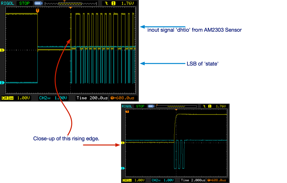
I am trying to write a verilog module to read data from an AM2303 (also
DHT22) temperature and humidity sensor.

The Am2303.v verilog code is attached, along with some images from my
oscilloscope.

In the verilog module I use a 7-bit register called "state" to implement
a state machine.

The oscilloscope image shows the inout signal "dhtio" as it comes from
the sensor, you can see it is very clean. No bounce. It also shows the
lest-significant-bit of "state" so that you can see exactly when "state"
changes.

I don't understand why state changes six times on the first rising edge
of the signal from the sensor.

I expected my state machine to stall at state 8'h02 until the signal was
high, and then stall at state 8'h03 until the next falling edge.

But as you can see it progresses from state 2 to 7 very rapidly.
Can anyone help me understand this?
Attached files:
-

scope_data.jpg
330 KB
Kenny Millar wrote:
> But as you can see it progresses from state 2 to 7 very rapidly.
Is the simulation of this design working flawlessly?

> Can anyone help me understand this?
You must synchronize external input signals (e.g. dhtin) before using
them inside. Otherwise this will happen:
http://www.lothar-miller.de/s9y/archives/64-State-Machine-mit-asynchronem-Eingang.html
(try Google translator, its German).

The input signal dhtin is connected to several FSM stages. Each of them
is represented by a flipflop inside the FPGA. And the propagation time
from the input pin to the corresponding state logic differs. Therefore
some flipflops see the "old" dhtin value, others see the "new" dhtin.
this will result in strange behaviour...
Thank you, that makes sense.

I haven't completed a simulation, because I'm just a newbie and still
learning how to simulate the sensor I/O in Lattice Diamond.

So if I change:
    assign dhtin = dhtio;

to:
    always @posedge(clk) begin
        dhtin = dhtio;
    end


I think that will synchronize the input signal?
Kenny Millar wrote:
> I think that will synchronize the input signal?
It looks like then you will have one FF sync stage. But I'm merely the
VHDL man... ;-)

BTW:
When you always get the very same picture, there also may be an
additional structural flaw in the description.
Lothar Miller wrote:
> Kenny Millar wrote:
>> I think that will synchronize the input signal?
> It looks like then you will have one FF sync stage. But I'm merely the
> VHDL man... ;-)
>
> BTW:
> When you always get the very same picture, there also may be an
> additional structural flaw in the description.

I do always get the same results, which is why I originally posted here
- the synchronisation of the input signal may be a red-herring, since
even with the change I mentioned above, I still get exactly the same
behaviour.
I will experiment with double-synchronisation, but I think I might still
see the same behaviour. I'm pretty new to verilog code, so was hoping
someone here might be able to help me understand why my state machine
progresses through states 2 to 7 so quickly, and doesn't do what I
expect - ie stall at each stage until the "dhtin" signal changes.

In the meantime, I will try double-synchronisation and see if that
helps.
the initial statement does not belong to the synthesizable subset.
1 | initial begin |
2 | count = 32'b0; |
3 | state = 8'h00; // once only condition |
4 | dataBits = 40'd0; |
5 | bitCount = 8'd40; |
6 | dht_oe = 1'b0; |
7 | dataReady = 1'b0; |
8 | end |
If you have it only included to assist with simulation, that is fine.
But it is then advisable to uses directives to exclude it during
synthesis.

Starting with verilog 2001 you can use initializers, but check with the
synthesizer documentation.

Example:
1 | reg [7:0] state = 8'h00; |
What Lothar wrote about synchronization will definitely hit you (also
that you are using just a one stage ff).

However, I think there is yet another bug in your code, in line 74, you
probably meant the inverted input for dhtin instead of the xor operator
you used, which would be the "~" operator for bitwise operation and "!"
for a logical not (either one would work in your example)
1 | 8'h03: begin // wait for our signal to achieve SPACE AFTER MARK. |
2 | if (~dhtin) begin // line 74, was ^dhtin |
3 | count =0; |
If you want a two stage sync FF you could use something along this line:
1 | reg [1:0] dhtin_sync; |
2 | always @(posedge clk) begin |
3 | dhtin_sync <= {dhtin_sync[0], dhtin};
|
4 | end |
One last point:
For sequential processes, it is more common to use non blocking
assignments (as shown above)

Best regards,
Tschaebe
Lattice User wrote:
> the initial statement does not belong to the synthesizable subset.
>
>
1 | > initial begin |
2 | > count = 32'b0; |
3 | > state = 8'h00; // once only condition |
4 | > dataBits = 40'd0; |
5 | > bitCount = 8'd40; |
6 | > dht_oe = 1'b0; |
7 | > dataReady = 1'b0; |
8 | > end |
9 | > |
>
> If you have it only included to assist with simulation, that is fine.
> But it is then advisable to uses directives to exclude it during
> synthesis.
>
> Starting with verilog 2001 you can use initializers, but check with the
> synthesizer documentation.
>
> Example:
>
1 | > reg [7:0] state = 8'h00; |
2 | > |
OK thanks again.
I now have this for double-synch:
1 | reg dhtin, ds1, ds2; |
2 | always @(posedge clk) begin |
3 | ds2<= ds1; |
4 | ds1 <= dhtio; |
5 | dhtin <= ds2; |
6 | end
|
And I know that we go through state 0,1 then 2, otherwise the sensor
would not talk to us, and that we stall as expected in those states,
because we are using "count" not the dhtin signal to move forward. But I
still have it going rapidly from state 2 to 7 when dhtin cannot be
changing?? I don't understand!

Could it be due to the inout signal? Have I misunderstood how that
works? I'm using
1 | assign dhtio = dht_oe ? 1'b0 " 1b'Z |
to tri-state the output when I'm not driving it.

Please forgive my complete newbie-ness!
Our posts overlapped - and believe it or not, I was just reading about
logcal / bitwise operators in the excellen "Introduction to Verilog" and
had just started wondering if I had the wrong operator.

Let me go fix those things, and I'll get back to you.
Thanks again for all your help.
This now works as expected :-)

The problem was indeed the wrong operator (^) instead of (~).
The full code now looks like the attached .v file.

I also changed to double synchronisation, and non-blocking assignments
and now it is working exactly as expected.

Now to do something useful with the data....
Please log in before posting. Registration is free and takes only a minute.
Existing account
Do you have a Google/GoogleMail account? No registration required!
Log in with Google account
Log in with Google account
No account? Register here.