EmbDev.net

Forum: FPGA, VHDL & Verilog 16 bit PISO register


von Omar Rashad (Guest)


Rate this post
useful
not useful
I am trying to write the VHDL code for a synchronous 16 bit register 
(SIPO, asynchronous reset) to use it as a component in another Serial 
Multiplier code.

I have been struggling with 'U' output on my signal:

code:
1
library ieee;
2
use ieee.std_logic_1164.all;
3
4
entity ShiftRegister is
5
  port(A: IN std_logic_vector (15 downto 0);
6
       clk,load,reset: IN std_logic;
7
       Y: OUT std_logic);
8
end ShiftRegister;
9
10
architecture behavior of ShiftRegister is
11
signal tmp: std_logic_vector(15 downto 0);
12
begin
13
tmp <= (others => '0');
14
15
process (reset,clk)
16
begin
17
  if (reset = '1') then
18
    Y <= '0';
19
  end if;
20
end process;
21
22
process (load, A)
23
begin
24
  if (load = '1') then
25
    tmp <= A;
26
  else 
27
    tmp <= (others => '0');
28
  end if;
29
end process;
30
31
process (clk)
32
begin
33
if (clk = '1' and clk'EVENT) then
34
  Y <= tmp(0);
35
  tmp <= '0' & tmp(15 downto 1);
36
end if;
37
end process;
38
39
40
end behavior;

Test Bench:
1
library ieee;
2
use ieee.std_logic_1164.all;
3
4
entity tb_ShiftRegister is
5
end tb_ShiftRegister;
6
7
architecture behavior of tb_ShiftRegister is
8
component ShiftRegister
9
  port(A: IN std_logic_vector(15 downto 0);
10
       clk,load,reset: IN std_logic;
11
       Y: OUT std_logic);
12
end component;
13
14
signal A: std_logic_vector (15 downto 0);
15
signal clk,load,reset,Y: std_logic:= '0';
16
17
begin
18
clk <= not clk after 10 ns;
19
DUT: ShiftRegister port map (A,clk,load,reset,Y);
20
process
21
begin
22
  wait for 0 ns;
23
  reset <= '1'; load <= '1'; A <= "1010101010101010";
24
  wait for 320 ns;
25
  --A <= "1111000011110000";
26
  --wait for 320 ns;
27
end process;
28
end behavior;

:
von Omar Rashad (Guest)


Rate this post
useful
not useful
*PISO

correction!

von Omar Rashad (Guest)


Rate this post
useful
not useful
Here is what I've managed to code (still no go). The processes do not 
seem to return different Y values but I still get 'U'
1
library ieee;
2
use ieee.std_logic_1164.all;
3
4
entity ShiftRegister is
5
  port(A: IN std_logic_vector (15 downto 0);
6
       clk,load,reset: IN std_logic;
7
       Y: OUT std_logic);
8
end ShiftRegister;
9
10
architecture behavior of ShiftRegister is
11
signal tmp: std_logic_vector(15 downto 0):=(others => '0');
12
signal F: std_logic:='0';
13
begin
14
--tmp <= (others => '0');
15
16
process (reset,clk,A)
17
begin
18
if (reset = '1') then
19
  F <= '0';
20
elsif (clk = '1' and clk'event) then
21
  F <= tmp(0);
22
  tmp <= '0' & tmp(15 downto 1);
23
else
24
  F <= F;
25
end if;
26
end process;
27
28
process (load,A)
29
begin
30
if (load = '1') then
31
  tmp <= A;
32
end if;
33
end process;
34
Y <= F;
35
36
end behavior;

von Lothar M. (Company: Titel) (lkmiller) (Moderator)


Rate this post
useful
not useful
Omar Rashad wrote:
> but I still get 'U'
Now the question arises: What is 'U'?
'U'ndefined, 'U'seless, 'U'ncertain, 'U'ninitilized?
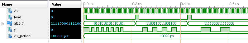
1
   reset <= '1'; load <= '1'; A <= "1010101010101010";
2
   wait for 320 ns;
Shouldn't you do anything with load and reset afterwards?

After having managed that you will encounter serious problems with this 
here:
1
architecture behavior of ShiftRegister is
2
signal tmp: std_logic_vector(15 downto 0);
3
begin
4
tmp <= (others => '0');            -- tmp is ALWAYS reset to all zero!
5
6
process (reset,clk)
7
begin
8
  if (reset = '1') then
9
    Y <= '0';
10
  end if;
11
end process;
12
13
process (load, A)
14
begin
15
  if (load = '1') then
16
    tmp <= A;                      -- ADDITIONALLY sometimes tmp gets the value of A
17
  else 
18
    tmp <= (others => '0');        -- if not is is reset to zero ONCE MORE
19
  end if;
20
end process;
21
22
process (clk)
23
begin
24
if (clk = '1' and clk'EVENT) then
25
  Y <= tmp(0);                                 
26
  tmp <= '0' & tmp(15 downto 1);   -- ADDITIONALLY sometimes its shifted with a clock
27
end if;
28
end process;
29
30
end behavior;
All in all: you drive tmp from three sources. That will not work! it 
will result in a collision. And
BTW: the very same is for Y! It is driven from two sources...
In fact you cannot reset Y because its the very same signal as tmp(0)!
Why should you need here a reset signal at all?

Try it that way and think hard about it:
1
architecture behavior of ShiftRegister is
2
  signal tmp: std_logic_vector(15 downto 0) := (others=>'0');
3
begin
4
  process (clk,load,A)
5
  begin
6
    if (load = '1') then
7
      tmp <= A;
8
    elsif (clk = '1' and clk'EVENT) then                              
9
      tmp <= '0' & tmp(15 downto 1);
10
    end if;
11
  end process;
12
13
  Y <= tmp(0);                                 
14
end behavior;

: Edited by Moderator
von Omar Rashad (Guest)


Rate this post
useful
not useful
Aren't all processes treated as concurrent statements within 
architecure? So only when one of the elements in the sensitivity list 
changes do they run again, correct? That means only processes with 
changes in their SL will get re-evaluated. Do I understand this 
correctly?

And the code that you provided (theoretically, I cannot simulate it now) 
does not work as intended. This is because tmp is reset to A everytime 
the process runs so we won't truly get the serial output of A, just 
continuous A(0)'s.

von P. K. (pek)


Rate this post
useful
not useful
Omar Rashad wrote:
> So only when one of the elements in the sensitivity list
> changes do they run again, correct? That means only processes with
> changes in their SL will get re-evaluated. Do I understand this
> correctly?

From the point of view how the Simulator calculates the result of each 
process this is correct, but: The other processes that are not 
re-evaluated still drive the signals (with the same not re-evaluated 
values as before).

In fact, it is only the simulator that makes use of sensitivity lists 
(to know when it needs to calculate new values). The hardware that 
results from synthesis just permanently "is there".

: Edited by User
von Lothar M. (Company: Titel) (lkmiller) (Moderator)


Rate this post
useful
not useful
Omar Rashad wrote:
> Do I understand this correctly?
Just for the simulation this is (nearly) correct. But in hardware each 
process is realized in parallel to each other process and "it" will 
drive its value all the time...

> And the code that you provided (theoretically, I cannot simulate it now)
> does not work as intended.
It works as far as my intention was: I load a value int the shift 
register by assigning a value to A and setting load to '1'. AFTERWARDS 
i set load to '0' and start clocking the data out. Got the trick?

And do you remeber my question:
Lothar Miller wrote:
>  reset <= '1'; load <= '1'; A <= "1010101010101010";
>  wait for 320 ns;
> Shouldn't you do anything with load and reset afterwards?

von Omar Rashad (Guest)


Rate this post
useful
not useful
I understand. But the assignment requires that Load remains 1 when we 
are clocking out an output and 0 if we want to clear the register.

von Lothar M. (Company: Titel) (lkmiller) (Moderator)


Rate this post
useful
not useful
Omar Rashad wrote:
> But the assignment requires
Which one?
> that Load remains 1 when we are clocking out
> an output and 0 if we want to clear the register.
And how do you LOAD data to the shift register? And if load also 
clears the register: what is the reset for?

von Omar Rashad (Guest)


Rate this post
useful
not useful
By assignment I was referring to my assignment

Reset clears the output to zero regardless of load. When reset is zero, 
content is zero if load is zero and is filled with Din when load is one. 
That is why load and A are in a separate process that is sensitive to 
both but not reset or clock.

von Lothar M. (Company: Titel) (lkmiller) (Moderator)


Rate this post
useful
not useful
Omar Rashad wrote:
> When reset is zero, content is zero if load is zero and is filled with
> Din when load is one.
A very unusual behavior. For a pity there is no hardware inside a FPGA 
able to handle such behavior...

> That is why load and A are in a separate process
> that is sensitive to both but not reset or clock.
You think the wrong way! You cannot control hardware stucture with the 
sensitivity list. The sensitivity lust is only relevant for the 
simulator.

von Omar Rashad (Guest)


Rate this post
useful
not useful
Are you saying I cannot use both load and reset?

von Omar Rashad (Guest)


Rate this post
useful
not useful
Can you show me a code you would write to describe a PISO 16 bit 
register (clocked) ?

von Lothar M. (Company: Titel) (lkmiller) (Moderator)


Rate this post
useful
not useful
Omar Rashad wrote:
> Can you show me a code you would write to describe a PISO 16 bit
> register (clocked) ?
I did already. Tomorrow I will provide a simple testbench for it...

von Lothar M. (Company: Titel) (lkmiller) (Moderator)


Attached files:

Rate this post
useful
not useful
Ok, here we go.
My spec is:
1. when load is '1' then load the vector A to the shift register
2. when load is '0' then shift out the data bit LSB first through Y
And this is the result:
1
library IEEE;
2
use IEEE.STD_LOGIC_1164.ALL;
3
4
entity Piso is
5
    Port ( clk :  in   STD_LOGIC;
6
           load : in   STD_LOGIC;
7
           A :    in   STD_LOGIC_VECTOR (15 downto 0);
8
           Y :    out  STD_LOGIC);
9
end Piso;
10
11
architecture Behavioral of Piso is
12
13
  signal sr: std_logic_vector(15 downto 0) := (others=>'0');
14
15
begin
16
17
  process (clk,load,A)
18
  begin
19
    if (load = '1') then
20
      sr <= A;
21
    elsif rising_edge(clk) then
22
      sr <= '0' & sr(15 downto 1);
23
    end if;
24
  end process;
25
26
  Y <= sr(0);      
27
 
28
end Behavioral;

Using this testbench I get the waveform in the screenshot:
1
LIBRARY ieee;
2
USE ieee.std_logic_1164.ALL;
3
 
4
ENTITY tb_piso IS
5
END tb_piso;
6
 
7
ARCHITECTURE behavior OF tb_piso IS 
8
 
9
    COMPONENT Piso
10
    PORT(
11
         clk : IN  std_logic;
12
         load : IN  std_logic;
13
         A : IN  std_logic_vector(15 downto 0);
14
         Y : OUT  std_logic
15
        );
16
    END COMPONENT;
17
18
   signal clk : std_logic := '0';
19
   signal load : std_logic := '0';
20
   signal A : std_logic_vector(15 downto 0) := (others => '0');
21
   signal Y : std_logic;
22
23
BEGIN
24
 
25
   uut: Piso PORT MAP (
26
          clk => clk,
27
          load => load,
28
          A => A,
29
          Y => Y
30
        );
31
32
   clk <= not clk after 5 ns;
33
34
   process  begin    
35
      A <= x"5555";
36
      load <= '1';
37
      wait for 15ns;
38
      load <= '0';
39
      wait for 200ns;
40
41
      A <= x"CCCC";
42
      load <= '1';
43
      wait for 15ns;
44
      load <= '0';
45
      wait for 200ns;
46
47
      A <= x"F0F0";
48
      load <= '1';
49
      wait for 15ns;
50
      load <= '0';
51
      wait for 200ns;
52
53
      wait;
54
   end process;
55
56
END;

The PISO is synthesizeable and results in 16 D-Flipflops with 
asynchronous clrear and preset inputs, which are controlled from A with 
a little glue logic. See the RTL schematic for this result...

: Edited by Moderator
Please log in before posting. Registration is free and takes only a minute.
Existing account
Do you have a Google/GoogleMail account? No registration required!
Log in with Google account
No account? Register here.