EmbDev.net

Forum: FPGA, VHDL & Verilog Servomotor. PWM and VHDL


von Soko L. (Company: sokoban) (gilgamesh)


Rate this post
useful
not useful
Hi:

I'm trying to control a servomotor HS-645MG with the Altera FPGA DE0 
using VHDL. According to my limited knowledge (and according to other 
programmers) these are the code for frequency dividing and pwm:

Frequency divider:
1
library IEEE;
2
use IEEE.STD_LOGIC_1164.ALL;
3
 
4
entity clk64kHz is
5
    Port (
6
        clk    : in  STD_LOGIC;
7
        reset  : in  STD_LOGIC;
8
        clk_out: out STD_LOGIC
9
    );
10
end clk64kHz;
11
 
12
architecture Behavioral of clk64kHz is
13
    signal temporal: STD_LOGIC;
14
    signal counter : integer range 0 to 4999 := 0;
15
begin
16
    freq_divider: process (reset, clk) begin
17
        if (reset = '1') then
18
            temporal <= '0';
19
            counter  <= 0;
20
        elsif rising_edge(clk) then
21
            if (counter = 4999) then
22
                temporal <= NOT(temporal);
23
                counter  <= 0;
24
            else
25
                counter <= counter + 1;
26
            end if;
27
        end if;
28
    end process;
29
 
30
    clk_out <= temporal;
31
end Behavioral;

PWM
1
library IEEE;
2
3
use IEEE.STD_LOGIC_1164.all;
4
use IEEE.STD_LOGIC_unsigned.all;
5
6
-----------------------------------------------------
7
8
entity pwm is
9
  port(
10
    clr : in std_logic;
11
    clk : in std_logic;
12
    duty : in std_logic_vector (7 downto 0);
13
    period : in std_logic_vector (7 downto 0);
14
    pwm : out std_logic
15
  );
16
17
end pwm;
18
19
-----------------------------------------------------
20
21
architecture pwm of pwm is
22
23
signal count : std_logic_vector(7 downto 0);
24
25
begin
26
27
  cnt: process(clk, clr) -- 4 bit counter
28
  begin
29
    if clr = '1' then
30
      count <= "00000000";
31
    elsif clk'event and clk = '1' then
32
      if count = period -1 then
33
        count <= "00000000";
34
      else
35
        count <= count +1;
36
      end if;
37
    end if;
38
  end process cnt;
39
40
  pwmout: process(count, duty)
41
  begin
42
    if count < duty then
43
      pwm <= '1';
44
    else
45
      pwm <= '0';
46
    end if;
47
  end process pwmout;
48
49
end pwm;

Top-design code
1
-----------------------------------------------------
2
3
library IEEE;
4
5
use IEEE.STD_LOGIC_1164.all;
6
use IEEE.STD_LOGIC_unsigned.all;
7
8
-----------------------------------------------------
9
10
entity pwm_top is
11
  port(
12
    clr : in std_logic;
13
    clk : in std_logic;
14
    duty : in std_logic_vector (7 downto 0);
15
    pwm : out std_logic
16
  );
17
18
end pwm_top;
19
20
-----------------------------------------------------
21
22
architecture pwm_top of pwm_top is
23
24
signal new_clock : std_logic;
25
26
begin
27
28
clk_div: entity work.clk64kHz
29
    port map(
30
      clk => clk, reset => '0', clk_out => new_clock);
31
32
Pulse: entity work.pwm
33
    port map(
34
      clr => clr, clk => new_clock, duty => duty, period => "11001000", pwm => pwm);      
35
      
36
end pwm_top;

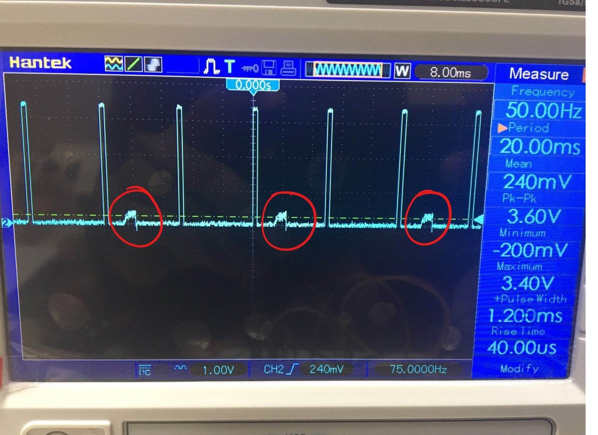
Described with my own words, the frequency is divided by a 5000 factor 
which yields to a new frequency of 10000Hz (0.1ms). Then the period of 
the pwm is assigned as 200 so the frequency of pwm will be 20ms and the 
duty cycle will be controlled with the DE0 built-in switches.

Unfortunately this doesnt work very well when the servo is connected, 
for example, if the duty cycle is 0.5ms the servo is supposed to moved 
to one end but instead, it seems to take a 45º position. For every other 
position, the servo also moves but it doesnt move accordingly to the 
duty cycle.

I have tested the servo with an arduino uno and works wonders.

What could be the problem?

Any ideas are welcomed.

von Lothar M. (Company: Titel) (lkmiller) (Moderator)


Attached files:

Rate this post
useful
not useful
What does the simulation tell you? Do you get what you expect?

What output level do you have? What level does the servo need?

Soko Loko wrote:
> clk64kHz
This ist NOT the way Clocks are generated in FPGA. Use the ONE and ONLY 
50MHz clock in the entire design and use clock enable signals for all 
slower counters.
Have a look at the attached file. Its does almost the same like yours. I 
made it for playing a little with such a servo: the 4 buttons change the 
PWM...

von FPGA advisor (Guest)


Rate this post
useful
not useful
did you figure out already if you PWM physical suits your application? 
typically servo motor controls wor with PDM rather PWM in order to 
overcome certain issues caused by non linear torque behaviour.

von Ankit Patel (Guest)


Rate this post
useful
not useful
please share something useful for cyclon 3 to servo motor programming.

von Prakash C. (Company: Newbie) (prakash_kadri)


Rate this post
useful
not useful
Lothar M. wrote:
> What does the simulation tell you? Do you get what you expect?
>
> What output level do you have? What level does the servo need?
>
> Soko Loko wrote:
>> clk64kHz
> This ist NOT the way Clocks are generated in FPGA. Use the ONE and ONLY
> 50MHz clock in the entire design and use clock enable signals for all
> slower counters.
> Have a look at the attached file. Its does almost the same like yours. I
> made it for playing a little with such a servo: the 4 buttons change the
> PWM...


Hi, I am new to VHDL programming. In your program can you help me to 
understand how you arrived these integer ranges?

signal divrel  : integer range 0 to 1500 := 1;
signal div1us  : integer range 0 to 49  := 0;
signal div1ms  : integer range 0 to 999 := 0;
signal div10ms : integer range 0 to 9   := 0;

von Lothar M. (Company: Titel) (lkmiller) (Moderator)


Rate this post
useful
not useful
Prakash C. wrote:
> Hi, I am new to VHDL programming. In your program can you help me to
> understand how you arrived these integer ranges
Most simple way: set up a simple test bench by supplying a clock and 
look at those counters.
A little bit harder: think about what those counters are used for...

> signal div1us  : integer range 0 to 49  := 0;
50MHz clock are 50 counts for one us.
> signal div1ms  : integer range 0 to 999 := 0;
A counter for 1000us...
> signal div10ms : integer range 0 to 9   := 0
A counter for each 10 milliseconds.
> signal divrel  : integer range 0 to 1500 := 1;
Don't know now, but simulation will show up the aim of this signal... ?

von Prakash C. (Company: Newbie) (prakash_kadri)


Rate this post
useful
not useful
Lothar M. wrote:
> Prakash C. wrote:
>> Hi, I am new to VHDL programming. In your program can you help me to
>> understand how you arrived these integer ranges
> Most simple way: set up a simple test bench by supplying a clock and
> look at those counters.
> A little bit harder: think about what those counters are used for...
>
>> signal div1us  : integer range 0 to 49  := 0;
> 50MHz clock are 50 counts for one us.
>> signal div1ms  : integer range 0 to 999 := 0;
> A counter for 1000us...
>> signal div10ms : integer range 0 to 9   := 0
> A counter for each 10 milliseconds.
>> signal divrel  : integer range 0 to 1500 := 1;
> Don't know now, but simulation will show up the aim of this signal... ?

Hi Lothar,

Thanks for the details. BTW I was able to burn this program into a chip 
and generated PWM signal. I am using Xilinx-Spartan-6. I am feeding the 
servo with external power supply of +5Volt & GND and connected the 
signal pin to the pin that I configured in my UCF File. GND of power 
supply and FPGA board is connected together.
But sometimes when I press the push button the servo doesn't rotate, 
instead I could feel some vibration inside the servo(May be it is trying 
to move). But if I give little push to the Servo Arm it moves. What may 
be the reason for this?  I am thinking it may be because of  my FPGA 
supplies signal at 3.3 Volt? Do i need to use level shifting from 3.3 
volt to 5volt? OR something wrong with my servo ?

Thank you

von Lothar M. (Company: Titel) (lkmiller) (Moderator)


Rate this post
useful
not useful
Prakash C. wrote:
> the servo doesn't rotate, instead I could feel some vibration inside
> the servo(May be it is trying to move). But if I give little push to the
> Servo Arm it moves.
Does that happen at the very same start position each time?

> I am thinking it may be because of  my FPGA supplies signal at 3.3 Volt?
You could check that with a signal generator supplying the same signal 
to the servo.

> OR something wrong with my servo ?
Sounds most likely...

von Prakash C. (Company: Newbie) (prakash_kadri)


Rate this post
useful
not useful
Lothar M. wrote:
> Prakash C. wrote:
>> the servo doesn't rotate, instead I could feel some vibration inside
>> the servo(May be it is trying to move). But if I give little push to the
>> Servo Arm it moves.
> Does that happen at the very same start position each time?
 No. It happens at different start position.
>> I am thinking it may be because of  my FPGA supplies signal at 3.3 Volt?
> You could check that with a signal generator supplying the same signal
> to the servo.
>
>> OR something wrong with my servo ?
> Sounds most likely...
I don't have signal generator at this moment.But I checked the Servo 
with the Servo tester. It works perfectly. I think servo is fine.

von Lothar M. (Company: Titel) (lkmiller) (Moderator)


Rate this post
useful
not useful
Prakash C. wrote:
> I think servo is fine.
Did you already check the signal at the servo input? If not: get a scope 
and do that.

And you also simply can use a transistor with a 5V pullup resistor as a 
"level shifter":
1
                                     
2
             3V3        5V                               
3
              o          o            
4
              |          |            
5
              -          -            
6
          2k2| |        | |2k2             
7
             | |        | |             
8
              -          -             
9
              |          |             
10
             ---         |             
11
             V \         |             
12
        -----   ---------o------------             
13
                                     
14
   FPGA                               Servo
15
                                     
16
        -----------------o------------                                  
17
                         |            
18
                        ---

von Prakash C. (Company: Newbie) (prakash_kadri)


Attached files:

Rate this post
useful
not useful
Lothar M. wrote:
> Prakash C. wrote:
>> I think servo is fine.
> Did you already check the signal at the servo input? If not: get a scope
> and do that.

Yes I did it. As I said before it was happening sometimes only.  After 
several trials I found this problem happens only when there is some 
noise in the PWM signal(photo attached). But surprisingly today when I 
pressed one push button this noise disappeared. Once the noise 
disappears the servo works fine. What you think the reason for this 
noise?

>
> And you also simply can use a transistor with a 5V pullup resistor as a
> "level shifter":
>
1
> 
2
>              3V3        5V
3
>               o          o
4
>               |          |
5
>               -          -
6
>           2k2| |        | |2k2
7
>              | |        | |
8
>               -          -
9
>               |          |
10
>              ---         |
11
>              V \         |
12
>         -----   ---------o------------
13
> 
14
>    FPGA                               Servo
15
> 
16
>         -----------------o------------
17
>                          |
18
>                         ---
19
> 
20
>

I ordered the level shifter online. Waiting for the delivery. :)

: Edited by User
von Prakash C. (Company: Newbie) (prakash_kadri)


Rate this post
useful
not useful
Lothar M. wrote:
> Prakash C. wrote:
>> I think servo is fine.
> Did you already check the signal at the servo input? If not: get a scope
> and do that.
>
> I replaced the servo motor and now i don't see this issue anymore. Looks like 
the issue was with the Servo itself.

Further i modified the program as below. The aim is the rotate the servo 
in one direction (180degree) and after certain time(c_CNT_delay) i want 
it to rotate in the reverse  direction and come back to the home 
position.
Need your help to find the bug in the below program.


library IEEE;
use IEEE.STD_LOGIC_1164.ALL;
use IEEE.NUMERIC_STD.ALL;

entity SPI_Servo is
    Port ( SERVO   : out  STD_LOGIC;
           i_clock  : in  STD_LOGIC);
end SPI_Servo;

architecture Behave of SPI_Servo is
signal divrel  : integer range 0 to 1500 := 1;
signal div1us  : integer range 0 to 49  := 0;
signal div1ms  : integer range 0 to 999 := 0;
signal div10ms : integer range 0 to 9   := 0;
signal us1     : std_logic;
signal ms1     : std_logic;
signal ms10    : std_logic;
signal flag  : std_logic := '0';
signal delay : std_logic := '0';

signal servocnt: integer range 0 to 20000 := 0; -- = 20ms
signal servoloc : std_logic;

constant c_CNT_delay   : natural := 250000000;
signal r_CNT_delay   : natural range 0 to c_CNT_delay;


begin

process begin
    wait until rising_edge(i_clock);
    us1  <= '0';
    ms1  <= '0';
    ms10 <= '0';
   if(div1us<49) then
       div1us <= div1us+1;
    else
       div1us <= 0;
       us1    <= '1';
       if(div1ms<999) then
          div1ms <= div1ms+1;
       else
          div1ms <= 0;
          ms1    <= '1';
          if(div1ms<9) then
             div10ms <= div10ms+1;
          else
             div10ms <= 0;
             ms10    <= '1';
          end if;
       end if;
    end if;
end process;

  -- every microsecond
  process begin
    wait until rising_edge(i_clock);
    if (us1='1') then
       if (servocnt<19999) then  servocnt<=servocnt+1;
       else                      servocnt<=0;

       end if;
   end if;
    if (servocnt=0)          then servoloc <= '1'; end if;
    if (servocnt=700 + divrel) then servoloc <= '0'; flag <= '1'; end 
if;

  end process;


 p_1_delay : process (i_clock) is
  begin
    if rising_edge(i_clock) then
      if r_CNT_delay = c_CNT_delay-1 then
          r_CNT_delay <= 0;
            delay <= '1';
      else
        r_CNT_delay <= r_CNT_delay + 1;
      end if;
    end if;
  end process p_1_delay;


process begin
    wait until rising_edge(i_clock);
    if(delay='1') then
       if(flag = '1' and divrel > 100) then divrel <= divrel-1; end if;
     else divrel <= 1500;
     end if;

end process;

SERVO  <= servoloc;
end Behave;

von Prakash C. (Company: Newbie) (prakash_kadri)


Rate this post
useful
not useful
hi,

If i want to increase the speed of servo to reach the desired position, 
what is the more efficient way to do it.

1) Is it by doing faster increment of signal divrel in the below 
process?
2) however i don't see considerable  increase in the speed if i  do 1). 
I checked my servo using servo tester board, and it is capable of 
rotating at faster rate.But I couldnot achieve the same in the code.
3) or there is any other approach.


  process begin
    wait until rising_edge(CLK50M);
    if(ms10='1') then
       if(BTN(0)='1' and divrel<1500) then divrel <= divrel+1; end if;
       if(BTN(1)='1' and divrel>100)  then divrel <= divrel-1; end if;
       if(BTN(2)='1') then divrel <= 100;  end if;
       if(BTN(3)='1') then divrel <= 1500; end if;
    end if;
  end process;

Please log in before posting. Registration is free and takes only a minute.
Existing account
Do you have a Google/GoogleMail account? No registration required!
Log in with Google account
No account? Register here.