Guest
#3708898
Hi!

Is it possible to modelise a capacitor in vhdl without using vhdl-ams?
In order to analyse his effect on a system in simulation.

Thank you
capacitor in vhdl ?
Guest
#3708898
Hi! Is it possible to modelise a capacitor in vhdl without using vhdl-ams? In order to analyse his effect on a system in simulation. Thank you
Guest
#3708925
You can't model an analog component in VHDL. You can use AFTER to describe the delay a cap adds to your digital signals. angelo wrote: > In order to analyse his effect on a system in simulation. With "pure" VHDL it is not possible to perform such simulations. Of course you can make a model of a simple capacitor that may change a signal or a frequency directly. Which effect do you want to analyze at all? A capacitor alone does nothing. It must have a resistor or an inductance with it to change something...
Guest
#3709329
You could port a capacitor model to VHDL, but that would be very quirky.
And you don't need to, there are some tools that let you interface a
SPICE simulation with virtual hardware.
If you just want to simulate the analog behaviour of fast I/Os, you'd
rather go for the IBIS modelling approach. VHDL is only good at digital
stuff (I know this could cause arguments).

Greetings,

- Strubi
Guest
#3709335
you can simulate the load/discharge characteristics of a capacitor. When you have a RC-Element you can model it, but only on discrete points of time. http://en.wikipedia.org/wiki/Capacitor Lattice User wrote: > You can't model an analog component in VHDL. Why not? VHDL offers simulation with "fs" granularity. This is more than sufficient for simulating the analog behavior of pretty complex circuits. For convenience this should be done in REAL to get most reasonable results and simulation time. For synthesizable code, the simulation becomes more coarse. Depending one the equation accuracy and eventual compensation of the issues caused by discrete time steps, one can achieve sufficient results for up to a 10th of the system speed, for full pipelined calculations. usually one can assume at least 1% of system speed taking into account the enough oversampling head romm which is required for filter applications. Some attention has to be payed in terms of error accumulation of course. With my VA-Synthesizers, electronic circuits were modeled at 768kHz sampling frequency with an average accuracy of more than 16 bits. Usually there were no significant difference between VHDL-ModelSIM results and pSPICE results when using the same equations (ideal components). Regarding an industrial design, resonators were successfully modeled with >100MHz and about 10Bits, using parallel calculation techniques. http://www.96khz.org/oldpages/vamodelling2.htm If there is enough time and only non realtime simulation is demanded, ModelSIM is sometimes even the better choice in comparison to MATLAB because of the higher calculation speed.
Guest
#3709686
Jürgen Schuhmacher wrote:
> Lattice User wrote:
>> You can't model an analog component in VHDL.
>
> Why not?


Yes I'm agree, my work is to design an analog model in vhdl using real.
The board I have to modelise is 90% analog. I thought vhdl can't help me
with capacitor or resistor but your answers make me change my mind.

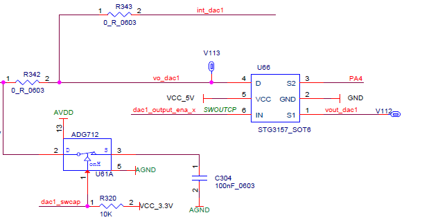
I provide a part of the design I have to modelise in attachment, so you
may help me to understand the effect of the capacitor in the system.

Thank you
Attached files:
Guest
#3709720
Hi, Have you ever heared of "Switched-Capacitor-Circuits"? Probably that's what you mean, when talking about of a simulation of an analog circuit in vhdl, such things also called analog-FPGA. http://en.wikipedia.org/wiki/Switched_capacitor angelo wrote: > but your answers make me change my mind. Keep in mind that Jürgen is very experienced with VHDL. How much time do you have for this task? > help me to understand the effect of the capacitor in the system. As far as I see it is a sample&hold capacitor. Or depending on what comes left a simple RC filter...
Guest
#3709770
Lothar Miller wrote:
> Keep in mind that Jürgen is very experienced with VHDL. How much time do
> you have for this task?

The global system takes part of an internship project, which end in
September but for this subsystem I would like to get over it in a few
days...

>> help me to understand the effect of the capacitor in the system.
> As far as I see it is a sample&hold capacitor. Or depending on what
> comes left a simple RC filter...

The left part is the analog output of a DAC
Guest
#3710310
if only the capacitor is of interest, a simple integrator /counter
design will do, i suppose.
Guest
#3710335
Modelling  in  vhdl-ams   is a nghtmare.
Go for  verilog-ams.

Here is the capacitor model


module cap(vp, vn);
inout vp, vn;
electrical vp, vn;
parameter real c = 0;

   analog
      I(vp, vn) <+ ddt(c*V(vp, vn));
endmodule
experto wrote: > if only the capacitor is of interest, a simple integrator /counter > design will do, i suppose. An integrator was not the right thing here. Basically it is a IIR-behaviour with saturation like this: if clk then condenser_voltage <= condenser_voltage * (1-x) + driving_voltage * x, where ratio X is obtained from the parameters C and R. i want work with ISE , and my question is can i simulate the analog circuit by use of schematic in ise? That is not a question of schematic entry but related to the limits of discrete timing and accuracy of the model (VHDL/VERILOG) you are going to provide to the simulator. Regarding ISE, there is an issue anyway: It has no analog view, so Vivado or ModelSIM should be focussed. Reply |