Hi,

I am working on a simple multi-channel pulse counter. The pulses counted
are infrequent (up to 100 kHz), and slow (at least 1 us), coming form a
comparator. In total I have 20 parallel channels (identical). Every 0.5
s I read out the counters and reset them to 0 using SPI.

The counter code is simple, contained in a module:
Some channels (not more than 3 out of 20) count two times the input
frequency. How is it possible? One channel is not counting properly at
all. I would expect the latter to be obviously caused by the speed of
arithmetic logic, but the former..?
  I am looking forward for your opinions.

  Regards,
  Krzysztof
Krzysztof wrote:> One channel is not counting properly at all.
How do the counting signals look like? Are there glitches or spikes on
the signals? Can you see ringing? How does the hardware look like?
Krzysztof wrote:> I am working on a simple multi-channel pulse counter. The pulses counted> are infrequent (up to 100 kHz), and slow (at least 1 us), coming form a> comparator. In total I have 20 parallel channels (identical). Every 0.5> s I read out the counters and reset them to 0 using SPI.
The design technology you use is due to its completely asynchronous
character tending to spurious failures.
To get reproducable results you must use a high speed clock (eg 50MHz)
and then synchronize all signals to that clock. Afterwards you should do
a denouncing and then an edge recognition to the signals. Then you can
count it.
The same syncing must be done with the SPI interface...
Hi,
the counted (raw) signal is already synchronized in oneshot module, in
the following manner (a very nice and reliable way - also checked with
the scope):
1
`timescale 1 ns / 1 ps
2
3
module oneshot (
4
input trigger,
5
input clock,
6
input en,
7
output reg q,
8
output wire out
9
);
10
11
wire m_trigger;
12
assign m_trigger = en & trigger;
13
14
reg r_out;
15
reg r_out1;
16
always @(posedge m_trigger, posedge r_out1)
17
begin
18
if (r_out1)
19
q <= 0;
20
else if (en)
21
q <= 1;
22
end
23
24
always @(posedge clock)
25
begin
26
r_out <= q;
27
r_out1 <= r_out;
28
end
29
30
assign out = q;
31
32
endmodule
Then the synchronized signal q is fed to the fast counter (q => load):
and there are no glitches - I watch the trigger (input signal) on the
scope instantly. The hardware is a LVPECL comparator, and the signal
source is a laboratory pulse generator - in all points of the HW the
signal is clean and very nice (also the LVPECL). A hint: depending on
the minor changes in order of module instantiation in Synplify Pro,
different channels count bad (double the freq. or completely wrong). The
main clock runs at 133 MHz, only the clock for the shifter is 399 MHz.

I've routed all trigger/gate/load signals out of the FPGA and watch them
on the scope - all of them are fine, in phase to the raw trigger and in
designed length (100 ns / 1 us). Only the last (slow!) counter fails.

The target is Lattice MachXO2 7000HE on their breakout board, the tool
chain is the latest Diamond 3.1 and Synplify Pro.
The SPI was not synced to the counters assuming that the readouts are
infrequent (2/s) compared to the trigger frequency - and bad readings
are always bad. But I do double buffer the counters using a built in
timer and synced to the global clock:
where counters are driven by the 20 slow_counter modules (4 are not
used), and countersSlave is fed to the SPI slave.

  I am really puzzled...

  Regards,
  Krzysztof
Krzysztof wrote:> A hint: depending on the minor changes in order of module instantiation> in Synplify Pro, different channels count bad
Now I'm sure: you have problems with asynchronous signals and/or
resets...
I'm a VHDL guy, but I would say: when there's a posedge, then there must
always follow the same clock. Same with the reset: only one reset must
be used.
To keep things short: 1 clock and 1 reset (if any is necessary) in the
whole design. Then your design will work...
There is only one reset, this is just my naming... Sorry for confusion.
The "reset" is asserted by the SPI command from a CPU controlling the
FPGA. The global reset is "slow_reset", clearing the counters every half
a second. But the clocking might be the issue, even though I am using
PLL generated clocks. But I'll try to use only one common clock.

Thanks for the hints!

  Regards,
  Krzysztof
Krzysztof wrote:> The global reset is "slow_reset", clearing the counters every half a> second.
That is a completely asynchronous design. You will not get reliable
function out of that.
> The global reset is "slow_reset"
No, that is not the "reset". The reset is a signal from the outside eg
from a button or a power manager.
What you have in your design is a lot of such things:
http://www.lothar-miller.de/s9y/archives/64-State-Machine-mit-asynchronem-Eingang.html
Try Google translator, its German...
One example how the design is broken, is how you generate and use
slow_gate.
1
always @(posedge clock, posedge trigger)
2
begin
3
if (trigger)
4
cnt <= delay;
5
else
6
if (slow_gate) begin
7
cnt[0] <= !cnt[0];
8
if (cnt[0] == 1'b1 ) cnt[7:1] <= cnt[7:1] - 1;
9
end
10
end
11
12
assign fin = (cnt == 0);
13
assign slow_gate = !fin;
14
15
always @(posedge slow_gate, posedge reset)
your slow_gate is generated from a big nand of your delay counter. But
due to signal length variations in the fpga not all inputs of this nand
change at the same time, which may result in glitches on slow_gate.

Also don't think you will be able to view this glitches with a scope,
even if you connect slow_gate to a fpga pin.
The fpga is internally much faster than on its pin. A glitch of only 1
ns can trigger the ff, but will not be visible outside the fpga.
Sorry for not posting the entire code at once and again - for the naming
- slow_reset should be called clear_counters or something like that. The
slow_reset is an internal signal, clocked by the main FPGA clock:
where the timeout is MachXO2 built-in timer. So it is synchronous. I am
using 1024 prescaler, so both timer signals last for long long time to
propagate etc...  Also, due to the phases between timeout_oc and
timeout_int, the first counters are stored in temporary countersSlave
reg, and then the slow_reset occurs.

(timeout_int occurs every 0.53 s, timeout_oc is 1 for 0.5 s, and then 0
for 0.03 s, then goes to 1 along with timeout_int event):
http://www.latticesemi.com/~/media/Documents/ApplicationNotes/UZ/UsingUserFlashMemoryandHardenedControlFunctionsinMachXO2Devices.pdf?document_id=39086
Table 9-8. PWM Waveform Generation.

Since the time needed for the countersSlave reg to latch the counters is
still much shorter (even assuming 100 ns) than the average rate of my
input pulses (no more than 10 kHz, at most it would be 100 kHz), I don't
think it might be the issue... But I will check this again.

  The other "real" reset is actually asserted only once at the beginning
on CPU request by the SPI module (one command sets the reset bit, the
other clears it, and that's all).

(I speak a little bit of German ;) - I'll have a look now.)

  So to sum up:
a) the raw pulses (not shorter than 5 ns by design, no more than 100
kHz) trigger properly the "oneshot" module - checked on the scope -
pulses are clear, not double triggered on glitches etc. - counted in
parallel to raw pulses by the digital scope properly - and thus
synchronized to the main clock.
b) the "oneshot" pulses are produced properly in the "shifter" module -
checked on the scope - 100 ns pulse width is OK, no double triggers etc.
- counted in parallel to raw pulses by the digital scope. And also
resynchronized.
c) the "slow_counter" pulses are also fine - 1-2 us width and no doubles
or missings etc. - counted in parallel to raw pulses by the digital
scope - and also they are fine.

As you can see - I've double-checked every step in the FPGA - especially
those vulnerable pieces of the design to timing issues - but I am still
missing something (it took me 2 months just to exclude all these
possible issues with synchronizing the raw signal). It still looks to me
as if either the counters are too slow to count the pulses
(unlikely...), or the countersSlave latches in some strange way the
values. I've checked the latter case easily - going down with the raw
pulse frequency down to few hundreds Hz (< 1kHz) - still the counter
counted e.g. 200 instead of 1000, or some of them double.

I won't believe Synplify makes mistakes. But what can be wrong with a
simple, 18-bit 100 kHz counter?

  Again, thanks for the interest - I will try all the hints since I am
helpless and out of ideas.

  Kind regards,
  Krzysztof
@Author: Lattice User (Guest)

  Thanks for the observation!

Well, that would explain a lot... Correct me if I am wrong, but then it
means that slow_gate may also trigger so many times that the counters
not only count fast, but fast enough to either double the results or
just screw them completely. One observation I made is that if the
counter shows bad number it is 99% of the cases a small number - that
was the reason I thought the carry chain was too slow, but as well it
might be that the counter rolls over.

  What would you suggest to do with the slow_gate - is it enough to sync
it with the clock?
Lattice User wrote:> A glitch of only 1 ns can trigger the ff
And the funny side of the coin is: maybe there's not enough energy in
that glitch to reset the whole counter. Probably only one or only the
of the FF is reset...
Krzysztof wrote:> What would you suggest to do
Try that ugly work around with the syncing flipflop. But best would to
kick away the counters design and rewrite it in a way completely
synchronous to "the clock". Even the counters should run with "the
clock". "The clock" is the already mentioned 50 KHz clock...
> the slow_gate - is it enough to sync> it with the clock?
No. The entire design must be synchronized to the "one and only" clock.
Let me say it this way: in a beginners design there is only 1 clock and
there's no reset. All external signals have to be synchronized to the
clock with two flipflops before they are used inside the FPGA.
Of course you can ignore those very simple rules. But sooner or later
you will get to where you ate now: a design, that reacts to minor
chances due to minor changes in the routing. A design that "works 99%
perfect, but...". Or a design, that only starts up every now and then,
but if it does, it runs well...
> it took me 2 months
It will take me one hour to write this fairly simple counter stage in a
way it will be bulletproof. But that won't help you, because then it
would be VHDL...
> I won't believe Synplify makes mistakes.
In most cases, when a C compiler makes problems, it is due to the C
program written by the user. The compiler is just doing what's written
down.
> But what can be wrong with a> simple, 18-bit 100 kHz counter?
Its not the synthesizer causing the problem. It is just making hardware
of what's written down.
Did you see my link? That is the problem. Now you can believe it or
not...
Hi,

yes, I see the problem clearly now.
Talking about the one hour work in VHDL: would you drop a few lines? I
can  compile mixed VHDL and verilog and see what comes out if you don't
mind (I am not too lazy to google, I am just overloaded with the
ideas/suggestions now...)

  Greetings,
  Krzysztof
I have the impesseion you got some old code for an ASIC and be tasked to
port it to a FPGA. The synopsys attributes are a hint for this, also the
tendency to turn every signal into a clock.

FPGAs have limited clock resources, so using a lot of clocks is
problematic. Also the FPGA Tools tend to spread your design over the
whole chip.

There are ways to control this and also to make sure an asynchronous
design is glitchfree, but this requires a lot of knowledge and many many
constraints. But doing this binds you to exactly one FPGA.

Following module is my suggestion:
It requires that the external pulses are longer than one clock period of
the clock. In your case longer than about 8-9 nsec.

It allows the counter to be read and cleared, without loss of count,
even in the case trigger_edge and read occur at the same clock cycle.
read_and_clear must be exactly one clock cycle long for this. At power
on the module needs one dummy read to initialize. (In VHDL you can use
initializers to avoid that dummy read).

The advantage for this approach is that you have ONE high speed clock
from which every thing is driven. As FPGAs and the tools are optimized
for this, you only need one constraint (the frequency of that clock) to
ensure every thing works fine.

(please note this may contain typos, i have not tried to compile it)
Lattice User wrote:> (please note this may contain typos, i have not tried to compile it)
Extent this to may contain ztypos and syntax errors, there is at least
one.
Hi,
the story behind my problem is a little bit different: I've been
programming embedded systems for quite some time already, and I did
exactly the same system in an ARM uController without any problems, in
less than a Sunday afternoon ;). Obviously the response times and
jitters due to the interrupts were present, but as you already know - it
is not meant to be the fastest system possible.
Then I thought of how about learning one of HDLs - verilog seemed
straight forward, but I also "read" VHDL easily now - just to improve
the system response time and jitter and profit from the speed of
CPLDs/FPGAs. So I took up the cheapest, the easiest (I thought so some
time ago...) CPLD for less than 20€ at Mouser's. That's how I ended in
implementing the design.
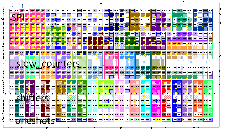
The choice of Lattice was also driven by the synthesis tool they give
off freely - Diamond + Synplify Pro are fully functional (I do use the
placement constraints, clock net constraints etc. - see the picture). I
was also playing around for a moment with the DE0 nano, but the IDE and
synthesizers are heavily limited. The Quartus e.g. does not allow to use
placement rules (simply ignores them), which are quite essential for my
design as I have already learned a lesson.
Now I will try to implement it in more synchronous way - so thanks for
the hint about the counter. I'll let you know about the results.
Greetings,
Krzysztof
Krzysztof wrote:> Hi,>> the story behind my problem is a little bit different: I've been> programming embedded systems for quite some time already, and I did> ....
You did think in hardware, which is a big step ahead of many other
beginners with a software background. Mostly they see VHDL/Verilog as
just another C-like programming language and fail to understand the
basics of digital hardware designs at all.
Krzysztof wrote:> So I took up the cheapest, the easiest (I thought so some time ago...)> CPLD for less than 20€ at Mouser's.
The MachXO has a FPGA structure with LUTs and flipflops, not a CPLD
structure with logic terms.
> The Quartus e.g. does not allow to use placement rules (simply ignores> them)
In reality this is no drawback. If you constrain your design correctly
you will not need such "intimate" tools in any way (this is like digging
around in machine code when writing software, yes machine code, not
assembler code...). I use such a tool once a year. And mostly only to
see, that I made a mistake in an earlier design step. For daily work
such a tool is useless.
Dear All,

please excuse my late response, but I was travelling to Germany.
The good news is that the code proposed by you for the counter with
synchronized trigger works... great! I had to adjust it to my needs just
a little bit.
  Once again - thank you for the interest and time devoted to the case.
I should say that by making this mistake I've learnt from practice much
more than from any ppt presentation I've seen over the Internet lately.
I'm thinking about starting a new project in FPGA so sooner or later I
will show up with another newbie questions.

  With kindest regards,
  Krzysztof