Sir, I am doing a project on DSP based fm receiver for my final year
project.
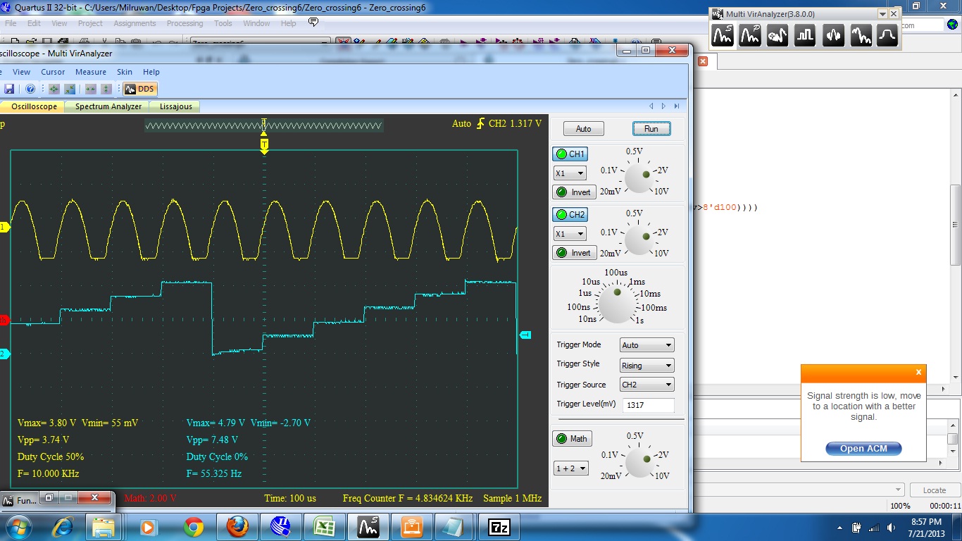
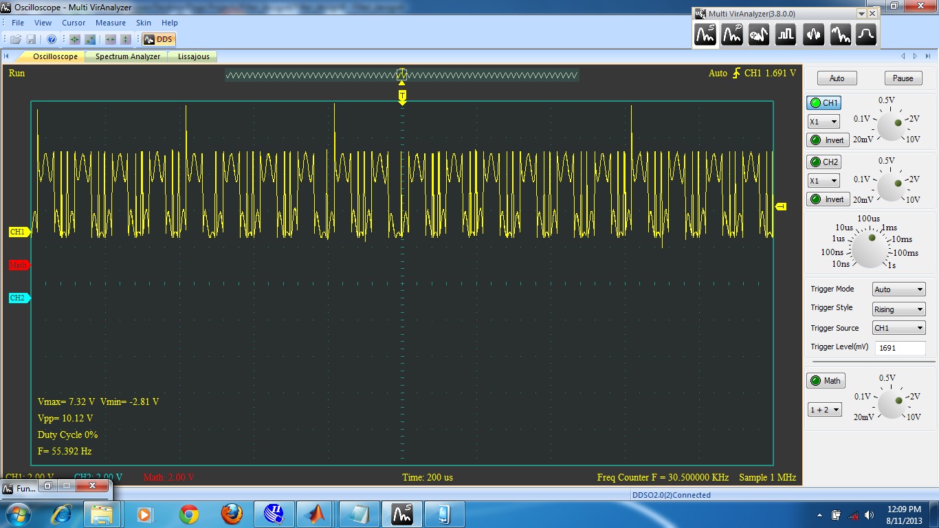
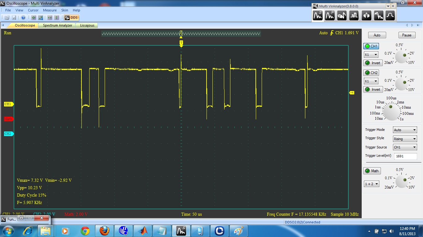
I want to demodulate the IF signal from the receiver and get the FM
multiplex signal. I am using zero crossing as the demodulation method.
According to the zero crossing algorithm I except a specific value for
specific frequency but this will give a ramp value, continuously varying
value for the output. I attach the oscilloscope view of the input and
the output(yellow-input blue-output). I want to get a constant value for
specific frequency. Please help me regarding this matter.
Hi Milruwan,

I miss the reset of timer2 if the condition

((((data_prv<8'd100
)&&(data_now>8'd100))||((data_now<8'd100)&&(data_prv>8'd100))))


becomes true. Therefore data_save advances as timer2. You could use the
difference between timer2 and data_save, but then you run in trouble if
timer2 wraps.

Furthermore you will experience difficulties if data_save varies around
8. Don't forget real signals are noisy, apply a hysteresis, only
filtering will not be sufficient.

Tom
I deleted the short and useless discussion about lazy pupils. But in
fact:
Milruwan Perera wrote:> I want to get a constant value for specific frequency.
With a litte bit of thinking and analyzing anybody can easily recognize,
that the steps (and therefore the difference) are the same. And now
there are two possible solutions:
calculate the difference between two steps and use that difference as a
result
OR
reset the counter with each (rising) edge
BTW:
Instead of building a monster comparator like this
a more experienced electrician would say: the most easiest to see a
zero-crossing in a signal way would be to look for the sign bit, which
is usually the leftmost bit in a signed integer. Then only two bits are
necessary to recongize the crossing: the actual sign bit and the
previous sign bit. And the whole comparator will result a 2 input XOR...
Hi..  Lothar Miller,

Thanks for your valuable reply.

I am getting the IF signal through ADC. Then how can I detect the rising
edge through 8bit samples (values from 0 to 255) that's why I use that
monster comparator. I observe that the mid value of the signal is 100.
Milruwan Perera wrote:> This is the code.
And whats the problem with it?
> If you have time please go through it and> let me know where I have went wrong.
Its fairly annoying to scan through an ugly formated code snippet with
no hint what it should do and what it does.
Why du you start each line of code at the leftmost position of a line?
That makes the code extremely unreadable: no way to see which end
belongs to which begin...
Milruwan Perera wrote:> I am getting the IF signal through ADC. Then how can I detect the rising> edge through 8bit samples (values from 0 to 255) that's why I use that> monster comparator. I observe that the mid value of the signal is 100.
I (as a more binary person) would take the step from 127 (=01111111) to
128 (=10000000) as the mid value (in fact with a FM signal that doesn't
matter). And now have a look for the "sign bit" (aka. MSB and aka. the
leftmost bit) of those two numbers: with 127 it is '0'. After crossing
the "zero-line" it is 128 and therefore '1'...
Lothar Miller wrote:> And whats the problem with it?
The problem is I don't get a constant value for specific frequency
through zero crossing detection. It is clearly shown in the picture I
had attached in the first conversation.
eg: assume for 10Khz zero crossing detected value should be 200 counts,
but the zero crossing detected value vary from 0 to 200
continuously.
Lothar Miller wrote:>> If you have time please go through it and>> let me know where I have went wrong.> Its fairly annoying to scan through a ugly formated code snippet with no> hint what it should do and what it does.> Why du you start each line of code at the leftmost position of a line?> That makes the code extremely unreadable: no way to see which end> belongs to which begin...
Thanks for telling this. I wrote those codes in order to test the code
is working for zero crossings. Now onwards I will write my every code in
a readable format.
Here is the full code used for zero crossing detection.
I'm a VHDL man, but this here seems to be some kind of "wait" statement.
Maybe this is simply not synthesizeable and therefore cnt_en results
in a static value of 1'b1 on your FPGA?
Lothar Miller,
Can you Please suggest me a method to to detect zero crossings in an
effective way.(In pseudo code or your comfortable VHDL code). It will be
really helpful to me.
> Can you Please suggest me a method
Did you at least think one second about my question?

>  It will be really helpful to me.
You have already a solution, you just have to get around that little
problem...

As already said: I'm doing VHDL and I'm pretty unknown to Verilog, but
taking your code I would try it by changing it this way:
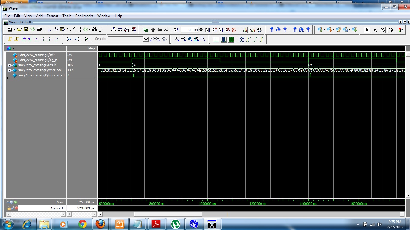
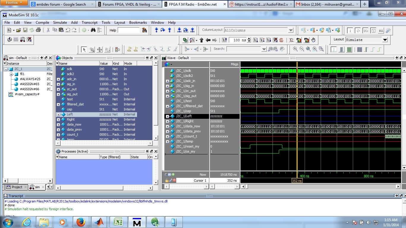
The following code is not resetting at when timer_reset==1'b1 ,Here I
attached the modelsim simulation result. I need to know where I went
wrong. Please help me.
Lothar Miller,
Can you please write a simple VHDL code to detect zero crossings(Similar
as the code in my previous post(Posted on: 2013-07-22 21:54)).The code I
wrote is not resetting the value of result register. I do not have a
VHDL code writing experience. So help me about this matter.
Hmm wrote:> a hint about non-synthesizable code.
Once more: forget about things like
#80
#100
#5000
#4000
in code that you want to run on hardware!
These "delays" are only good for simulation!
Milruwan Perera wrote:> Can you please write a simple VHDL code to detect zero crossings
Here you are, a short fingers excercise in the lunch break. Attached is
also the waveform of a testbench that modulates a sine which is handed
over to input. Then this FM sine is demodulated and results in the
output. There you see some granularity due to the used sampling
frequency...
Lothar Miller,
What is the simulator you are using? I think it is not modelsim. How do
you apply those Analog signal data to the testbench? I also wrote a
similar code Verilog but I don't know how to give an analog signal as
input and simulate in modelsim. May I know the steps you went through to
apply a Analog signal in.
Milruwan Perera wrote:> Lothar Miller, What is the simulator you are using? I think it is not> modelsim.
No, that was Active HDL from Aldec. But you can do that also with
ModelSim also.
> How do you apply those Analog signal data to the testbench?
Why did I know, that this question will arise? ;-)
I calculate the modulated fm sine. The output of this calculation is a 8
bit vector. This vector is input to the fm demodulator. And the analog
waveform is just an analog representation of that vectors value. You can
change that easily in the properties of the specific vectors waveform.
Here it is shown for ModelSim:
http://forums.xilinx.com/t5/General-Technical-Discussion/how-to-see-output-as-sine-wave-in-modelsim/td-p/65238> I also wrote a similar code Verilog but I don't know how to give an analog> signal as input and simulate in modelsim. May I know the steps you went> through to apply a Analog signal in.
1. calculate the (low frequency) modulation
2. calc the carrier frequency and modulate it with the result of 1.
3. scale the result to the desired vector
See the attached testbench.
Hi, I have some how manage to detect the zero crossings, but the problem
is it is not accurate to detect small frequency deviations, due to the
oscillator clock frequency. I need to know is it possible to change the
crystal to 100MHz? I am using the Altera EP2C8Q208C8 Fpga chip. I went
several times through the datasheet to determine the Oscillator
frequency, but I was not able.

Is Altera EP2C8Q208C8 Fpga chip can be driven with 100MHz crystal?
The chip can be driven with more than 100MHz.

But: can your design be driven with 100MHz after it is synthesised for
this chip?

A way to find that out is to set a constraint for the designs clock...
Milruwan Perera wrote:> Is Altera EP2C8Q208C8 Fpga chip can be driven with 100MHz crystal?
You obviously don't know anything about FPGAs and/or toolchains for
synthesis ...
Why did you choose a project you impossibly can do on your own?
In this project I need to take the IF signal and demodulate it in an
FPGA. In order to do the demodulation I need to amplify the IF signal
and get in to ADC resolution range (0V to 5V). Received IF signal
amplitude is 5mv and I need to amplify it to 5V. I ordered  THS3202 dual
current-feedback amplifier for the amplification process. But the
amplified output was a noisy signal ( I applied 10.7MHz  5mv sine wave
from the signal generator and try to amplify it to 1V).

1)  Can this be used to amplify 10.7MHz signal ?

2) Please suggest me a method to amplify the IF signal to 5V range?
Milruwan Perera wrote:> I applied 10.7MHz 5mv sine wave
What is this 5mV? RMS? Peak? Peak to peak?
> But the amplified output was a noisy signal
To amplify a signal by 1000 is a very demanding job. Decoupling of the
amplifiers stages (if there hopefully is more than one) is the primary
task. Can you show your schematics and post a picture of your assembly?
2) Please suggest me a method to amplify the IF signal to 5V range?
Read and understand AppNotes and UserGuides. Amplify it in two well
decoupled stages. Have a look for a low impedance design and a good
layout. Keep in mind that those GHz amps are little beasts...
See the decoupling there page 11:
http://www.ti.com/lit/an/slyt102/slyt102.pdf
And the sample layout on the last pages there:
http://www.ti.com/lit/ug/slou148/slou148.pdf
BTW:
If you are doing cross posts, then at least inform us and them about
that fact. And don't use either one as a "fall back option"...
BTW2:
> eilert> 07-21-2013 11:32 PM> #2 cnt_en<=1'b1;> I don't think this will work in synthesis.
And you posted on: 2013-07-22 11:10
> cnt_en<=1'b0;> #2 cnt_en<=1'b1;
That leads me to one question (I already asked):
Do you at least read the answers given to you?
Lothar Miller wrote:> If you are doing cross posts, then at least inform us and them about> that fact.
Sorry for cross posting. I have done this in order to get a better
solution for my problem.
Hi.. all these days I am designing the filters for my radio receiver
project. I used Matlab HDL coder for implementing the filters.

filter specification is shown below
1
//FilterSpecifications:
2
//
3
//SamplingFrequency:1.527MHz
4
//Response:Lowpass
5
//Specification:Fp,Fst,Ap,Ast
6
//PassbandEdge:50kHz
7
//StopbandEdge:60kHz
8
//PassbandRipple:1dB
9
//StopbandAtten.:100dB
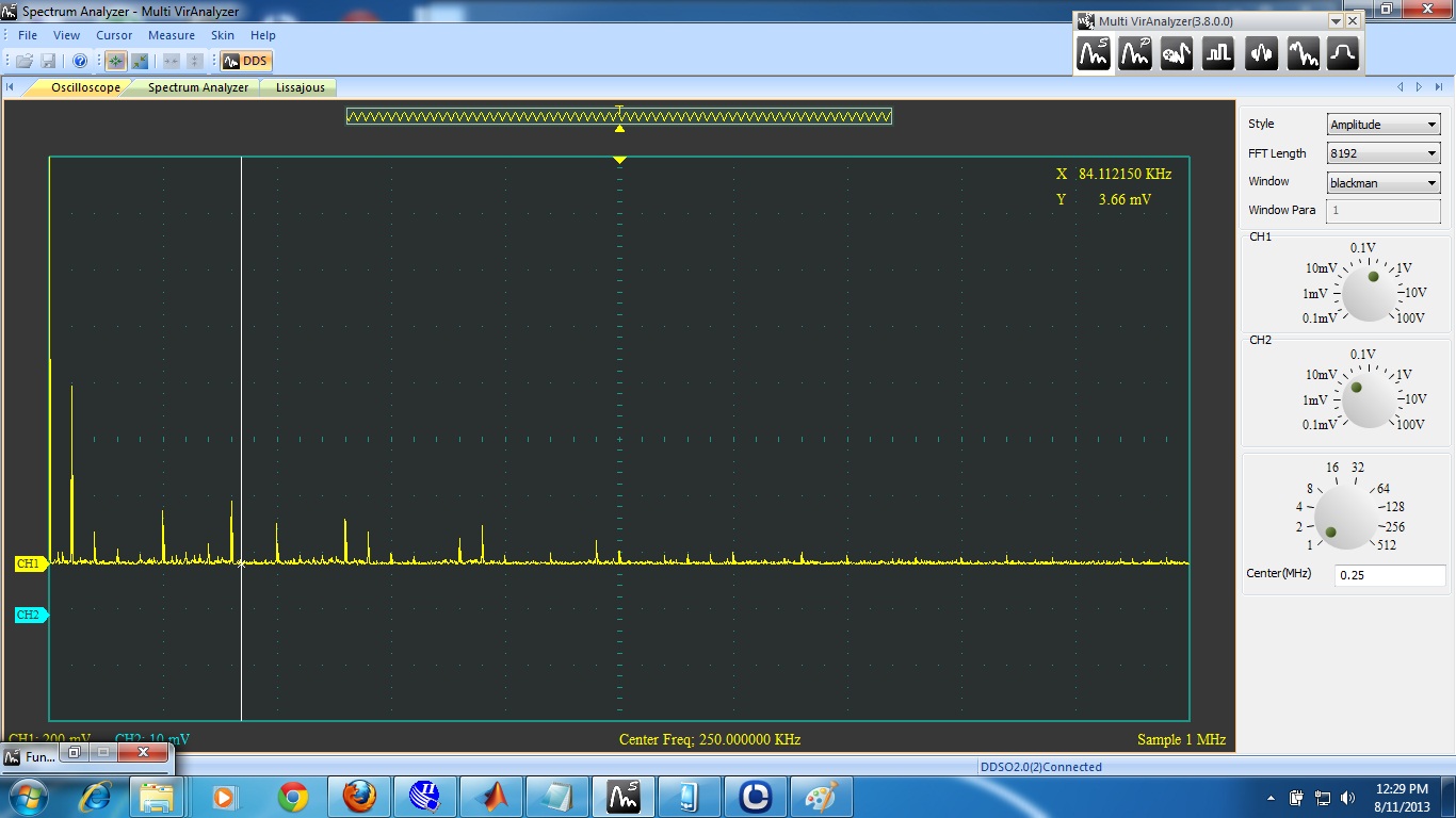
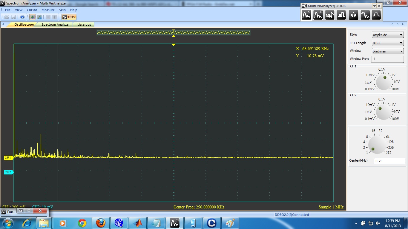
The proublem of this filter is, when I give a 10kHz input to this filter
it will generate more frequency components.
When I give 80kHz then it will filter(cutoff 60kHz) the 80kHz but it
will generate some frequency components lower than the cut-off
frequency.
What is the reason for this problem?
How can I design an accurate filters (LPF and BPF)?

The output of my filter is attached.
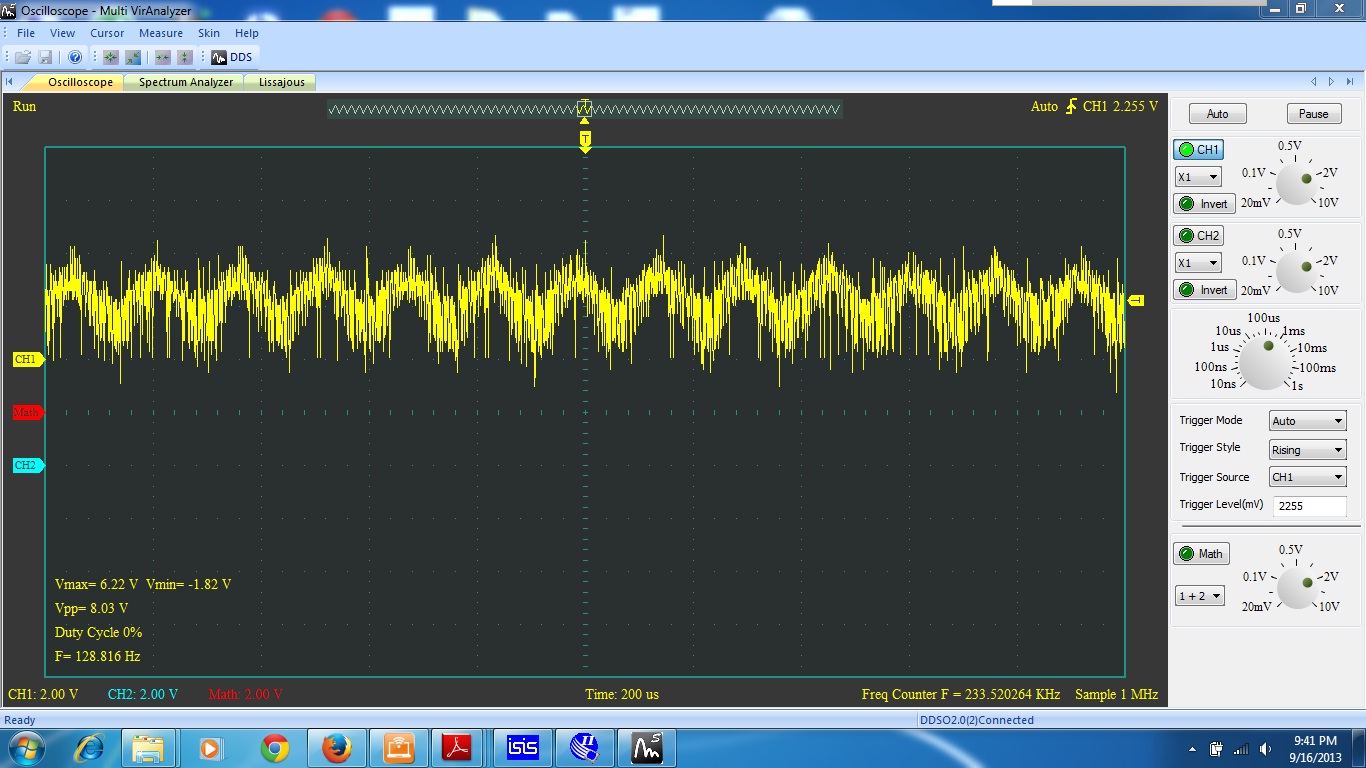
Hi... I detect the zero crossing using the actual hardware.But the
detected sine wave is a noisy signal.Here I attach the picture.Please
give your suggestions.
I implement a Zero crossing detector in a fpga. It can detect the zero
crossings of a signal and it could successfully demodulate a FM
modulated signal. The problem is the demodulated signal doesn't have a
fixed sample rate,Because when a zero crossing is met counter will
start. when the other zero crossing is met counter save the present
value to a register and restart the counter.This process will
continue.... The value of the register is the demodulated signal.But it
doesn't have a fixed sample rate. So the demodulated signal cannot be
filtered.

1) How to get a fixed sample rate?
2)What is the sample rate we should take as the sampling rate of the
filter?
3)How to overcome this problem?
The answer to all of the three questions is the same: oversampling
But to question 2 some additional questions arise:
- What frequencies are in your system?
- Whats the carrier frequency?
- Whats the signal frequency range?
Milruwan Perera wrote:> The problem is the demodulated signal doesn't have a fixed sample rate
Actually thats not a problem. You simply demodulate the fm signal and
look at the demodulated signal as if it is the "analog" output of an
externally connected demodulator. An external (analog) demodulator also
has no time relation to the filter inside the FPGA, and so the filter
itself takes the current input level and samples it with the filters
sampling frequency...
Lothar Miller wrote:> The answer to all of the three questions is the same: oversampling
Sorry sir in my question i forgot to say that I am doing the filtering
part inside the fpga (designing a digital filter). I am doing to do all
the processing inside the fpga.Due to the variable sample rate I could
not process the signal(filter the signal). What should I need to do?
Lothar Miller wrote:> But to question 2 some additional questions arise:> - What frequencies are in your system?> - Whats the carrier frequency?> - Whats the signal frequency range?
What frequencies are in your system? 300kHz center frequency with 50kHz
frequency deviation.
Whats the carrier frequency? 300kHz
Whats the signal frequency range? frequencies from 20Hz to 60kHz (FM
multiplex signal)
Milruwan Perera wrote:> Due to the variable sample rate I could not process the signal(filter> the signal). What should I need to do?
Just use the current demodulator output as input for the filter. You do
not have anything else...
Lothar Miller wrote:> Just use the current demodulator output as input for the filter. You do> not have anything else...
What should be the sampling rate (Fs) of the filter?
Milruwan Perera wrote:> What should be the sampling rate (Fs) of the filter?
It should be (according to Nyquist and Shannon) at least twice the
highest signal frequency...
I design a filter using Matlab hdl coder. But the problem is filter
doesn't give filtered output. When I do the simulation in matlab filter
works perfectly, but when I test with modelsim filter is not giving the
filtered output. Problem is with the way of resetting and enabling the
filter.

filter inputs and outputs

Code:
1
modulefilter
2
(
3
clk,
4
clk_enable,
5
reset,
6
filter_in,
7
filter_out
8
);
input_reg_process
Code:
1
always@(posedgeclkorposedgereset)
2
begin:input_reg_process
3
if(reset==1'b1)begin
4
input_register<=0;
5
end
6
elsebegin
7
if(clk_enable==1'b1)begin
8
input_register<=filter_in;
9
end
10
end
11
end//input_reg_process
Here is the output I got (reset and enable signal are also shown in the
figure)

reset_my : is the reset
ce_my: is the enable