
Hi to all,
A homework task I got is to create a component which receives
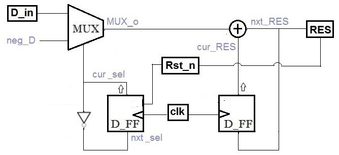
positive numbers and gives the output of A+B-C+D-E...
I got a few error's which seem to be all connected to each other,
but I don't manage to understand what the problem is.
The code is:
library ieee;
use ieee.std_logic_1164.all;
-- mux2to1 Component ----
-------------
entity mux2_1 is port
(d0 : in integer;
d1 : in integer;
sel : in bit;
d_out : out integer);
end entity;
architecture mux2_1_arc of mux2_1 is
begin
with sel select
d_out <= d0 when '0',
d1 when '1';
end architecture;
--------------------
library ieee;
use ieee.std_logic_1164.all;
use std.env.all;
-- d_ff for result Component ---- (integer input)
-------------
entity d_ff_res is port
(clk_ff : in std_logic;
d_ff_in_res : in integer;
d_ff_out_res : out integer);
end entity;
architecture w_sens_list of d_ff_res is
begin
process (clk_ff)
begin
if clk_ff'event and clk_ff='1' then
d_ff_out_res <= d_ff_in_res;
end if;
end process;
end architecture;
----------------------
library ieee;
use ieee.std_logic_1164.all;
use std.env.all;
-- d_ff for mux Component ---- (bit input)
-------------
entity d_ff_mux is port
(clk_ff : in std_logic;
d_ff_in_mux : in bit;
d_ff_out_mux : out bit);
end entity;
architecture w_sens_list of d_ff_mux is
begin
process (clk_ff)
begin
if clk_ff'event and clk_ff='1' then
d_ff_out_mux <= d_ff_in_mux;
end if;
end process;
end architecture;
----------------------
library ieee;
use ieee.std_logic_1164.all;
use ieee.std_logic_signed.all;
use std.env.all;
-- main Component ---
-----------------------
entity taylor_seq is generic (n : positive := 5);
port (D_in : in integer;
Rst_n : in std_logic;
clk : in std_logic;
RES : out integer );
end entity;
architecture arc_taylor_se of taylor_seq is
signal mux_o, last_RES, tran_RES : integer;
signal sel_mux, rev_sel : bit;
constant CCT : time := 10 ns;
begin
last_RES <= 0;
mux_o <= 0;
RES <= 0;
sel_mux <= '0';
tran_RES <= 0;
Rst_n <= '1';
rev_sel <= NOT sel_mux;
clk <= not (clk) after CCT / 2;
my_mux : entity work.mux2_1 port map (
d0 => D_in,
d1 => D_in,
sel => sel_mux,
d_out => mux_o);
MUX_DFF : entity work.d_ff_mux port map (
d_ff_in_mux => rev_sel,
d_ff_out_mux => sel_mux,
clk_ff => clk);
RES_DFF : entity work.d_ff_res port map (
d_ff_in_res => tran_RES,
d_ff_out_res => last_RES,
clk_ff => clk);
FAs_generator: for i in 1 to n generate
process (clk)
begin
if rising_edge (clk) then
if Rst_n='1' then
if sel_mux = '1' then
tran_RES <= last_RES+mux_o;
else
tran_RES <= last_RES-mux_o;
end if;
RES <= tran_RES;
else -- Rst_n= 0
RES <= 0;
Rst_n <= '1';
end if;
end if;
end process;
end generate;
end architecture;
and the compiler's response is:
** Error: ex4.vhd(98): Cannot drive signal 'Rst_n' of mode IN.
# ** Error: ex4.vhd(100): Cannot drive signal 'clk' of mode IN.
# -- Loading entity mux2_1
# -- Loading entity d_ff_mux
# -- Loading entity d_ff_res
# ** Error: ex4.vhd(134): Cannot drive signal 'Rst_n' of mode IN.
# ** Warning: [5] ex4.vhd(83): Nonresolved signal 'RES' may have
multiple sources.
# Drivers:
# ex4.vhd(95):Conditional signal assignment line__95
# ex4.vhd(120):Process line__120
# Driven at:
# ex4.vhd(130)
# ** Error: ex4.vhd(88): Nonresolved signal 'mux_o' has multiple
sources.
# Drivers:
# ex4.vhd(106):Statement my_mux
# ex4.vhd(94):Conditional signal assignment line__94
# ** Error: ex4.vhd(88): Nonresolved signal 'last_RES' has multiple
sources.
# Drivers:
# ex4.vhd(116):Statement RES_DFF
# ex4.vhd(93):Conditional signal assignment line__93
# ** Warning: [5] ex4.vhd(88): Nonresolved signal 'tran_RES' may have
multiple sources.
# Drivers:
# ex4.vhd(97):Conditional signal assignment line__97
# ex4.vhd(120):Process line__120
# Driven at:
# ex4.vhd(125)
# ** Error: ex4.vhd(89): Nonresolved signal 'sel_mux' has multiple
sources.
# Drivers:
# ex4.vhd(111):Statement MUX_DFF
# ex4.vhd(96):Conditional signal assignment line__96
# ** Error: ex4.vhd(139): VHDL Compiler exiting
# D:/Modeltech_pe_edu_10.2a/win32pe_edu/vcom failed.
thanks in advance, Amitai
Attached files:
-

__________________4.jpg
48 KB
I tend to say that the messages tell the problems fairly clear. Let's
take the clk:
You define it as an input:
 clk : in std_logic;
But a few lines later you want to drive the clock:
  clk <= not (clk) after CCT / 2;
Also keep in mind that after is NOT synthesizeable!
You can use it in a test bench, but you cannot transfer it to real
hardware.

Multiple sources are signals driven from more the one assignment.  And
that's not allowed in VHDL, and it cannot be transferred to hardware
because it would result in a short circuit of two output drivers...
Attached files:
-

3__________.jpg
34 KB
Thanks very much for the quick answer.

I understood the meaning of the clock- it needs to be
controlled from the testbench and not by the component itself.

The problem of the multiple sources I managed to Reduce to one-

# ** Error: checkex4.vhd(103): Nonresolved signal 'cur_RES' has multiple
sources.

which is the output of the FF whom is responsible for the memory
for the next cycle. I don't see why there is a problem with the code.
(I can guess it's connected to the clock and sync options ?)


Thanks, Amitai
amitai wrote:
> # ** Error: checkex4.vhd(103):
> Nonresolved signal 'cur_RES' has multiple sources.
To be exact: there are two sources. One here:
    cur_RES <= 0;
And the other here:
    d_ff_out   => cur_RES,

You have also a multiple source on cur_sel. Its very similar. You will
find it yourself now...

Also the sensitivity list of the process taylor_sequnce is completely
rubbish: clk is not used in the process at all, but rst_n, nxt_RES,
mux_o and cur_RES are missing. To keep things short: your simulation ist
totally WRONG! It will look like this process is someway related to clk,
but in hardware this process will result in a completely combinational
wiring.


According to your picture I would write the code this way:
1 | library ieee; |
2 | use ieee.std_logic_1164.all; |
3 | use ieee.std_logic_signed.all; |
4 | |
5 | entity taylor_seq is |
6 | port (D_in : in integer; |
7 | Rst_n : in std_logic; |
8 | clk : in std_logic; |
9 | RES : out integer ); |
10 | end entity; |
11 | |
12 | architecture arc_taylor_se of taylor_seq is |
13 | |
14 | signal d,r : integer; |
15 | signal invert: std_logic; |
16 | |
17 | begin
|
18 | d <= D_in; |
19 | |
20 | toggle_sign : process (Rst_n,clk) |
21 | begin
|
22 | if Rst_n='1' then |
23 | invert = '0'; |
24 | elsif rising_edge(clk) then |
25 | invert <= not invert; |
26 | end if; |
27 | end process; |
28 | |
29 | taylor_sequnce : process (Rst_n,clk) |
30 | begin
|
31 | if Rst_n='1' then |
32 | r <= 0; |
33 | elsif rising_edge(clk) then |
34 | if invert='0' then |
35 | r <= r+d; |
36 | else
|
37 | r <= r-d; |
38 | end if; |
39 | end if; |
40 | end process; |
41 | |
42 | RES <= r; |
43 | end architecture; |
Thats it, folks...


Of course you can write the code a little bit more chatty and split up
the code to the elements in the picture:
1 | library ieee; |
2 | use ieee.std_logic_1164.all; |
3 | use ieee.std_logic_signed.all; |
4 | |
5 | entity taylor_seq is |
6 | port (D_in : in integer; |
7 | Rst_n : in std_logic; |
8 | clk : in std_logic; |
9 | RES : out integer ); |
10 | end entity; |
11 | |
12 | architecture arc_taylor_se of taylor_seq is |
13 | |
14 | signal din,dneg,muxo,cr,nr : integer; -- data input ... current result, next result |
15 | signal cs, ns: std_logic; -- current and next sign |
16 | |
17 | begin
|
18 | din <= D_in; |
19 | dneg <= -D_in; |
20 | |
21 | -- the mux
|
22 | muxo <= din when cs='1' else dneg; |
23 | |
24 | -- the toggle bit inverter
|
25 | ns <= not cs; |
26 | |
27 | -- the toggle bit FF
|
28 | toggle_sign : process (Rst_n,clk) |
29 | begin
|
30 | if Rst_n='1' then |
31 | cs <= '0'; |
32 | elsif rising_edge(clk) then |
33 | cs <= ns; |
34 | end if; |
35 | end process; |
36 | |
37 | -- the adder
|
38 | nr <= cr + muxo; |
39 | |
40 | -- the result FFs
|
41 | process (Rst_n,clk) |
42 | begin
|
43 | if Rst_n='1' then |
44 | cr <= 0; |
45 | elsif rising_edge(clk) then |
46 | cr <= nr; |
47 | end if; |
48 | end process; |
49 | |
50 | RES <= cr; |
51 | end architecture; |
But why the heck sould anyone go as far as you did and implement a MUX
or some D-FF as stand-alone components/modules?
I tried using your code and changed it,
because of a few things:
- the meaning of the question I got is that the whole process
  happens after the rising clock ( including the reset)

- as far as I understand, different process work in parallel
  and what I need is that there will be one process which has
  a sync between the 2 parts

The program still doesn't work as expected and the output
has for some reason different clock time then the rest of the
circuit, any idea why?

Thanks, Amitai

PS - the idea of implementing by mux etc. is of the lecturer for some
reason
> that the whole process happens after the rising clock
A process does not "happen". A process is transferred to real hardware
and that is "always there". So in hardware a process is "executed
always".
But in simualtion a process is recalculated when any one of the
signals in the sensitivity list changes (you will need this information
later for your "delayed output" problem).

> different process work in parallel
Of course they "work in parallel", because every process will result in
a piece of silicon with the described function.

> The program
It is not a "program" (thats a term out of the software world!). What
you have is a "hardware description". If VHDL would be a programming
language it would be called VHPL...

> still doesn't work as expected
And so: what do you get?

> and the output has for some reason different clock time then the rest
> of the circuit, any idea why?
One blink with the eyes, and there it is. Thats a fake clock due to an
incomplete sensitivity list.
Try it this way and think about it:
1 | :
|
2 | :
|
3 | toggle_sign : process (clk) |
4 | begin
|
5 | if rising_edge(clk) then |
6 | if Rst_n='0' then |
7 | :
|
8 | end if; |
9 | end if; |
10 | end process; |
11 | |
12 | RES <= cr; |
You see the problem?
> I tried using your code /and changed it/
You changed it without understanding what you are changing.
You could do it also this way by completing the sensitivity list:
1 | :
|
2 | :
|
3 | toggle_sign : process (clk,cr) |
4 | begin
|
5 | if rising_edge(clk) then |
6 | :
|
7 | end if; |
8 | RES <= cr; |
9 | end process; |
But you should not mix combinatorial and synchronous parts in one
process. Thats a good reason to get fired...

> PS - the idea of implementing by mux etc. is of the lecturer for
> some reason
Yes, thats the usual stupid academic structural description style from
the end of the last millennium. And thats why VHDL is called to be a
chatty language. No further comment...

BTW: you have a major difference now in your design vs. my design. Your
reset is synchronous, mine is asynchronous. I don't know which one fits
to your picture. But your first VHDL descripiton was totally
asynchronous. And perhaps that was also the intention of your lecturer.
Synchronous vs. asynchronous reset is another big chapter in hardware
desription. But you will not hear anything about it in school...
Please log in before posting. Registration is free and takes only a minute.
Existing account
Do you have a Google/GoogleMail account? No registration required!
Log in with Google account
Log in with Google account
No account? Register here.