Dear all,
I am in trouble with ADC module. I try to code a very simple code:

module dac_test(

input clk,
output [13:0] dac

);

assign dac = 14'b11110001010110;

endmodule


with clk is 1Mhz clock and I mapped it into PIN_B15, and the 14bit data
dac, I mapped it into 14 pin of U14. I sure that after I install like
this, I totally get the logic level in U14's pins as in the code, and I
also check the clock at pin 28 of U14. It is OK.

However, I use the VOM try to get the analog output voltage of DAC
(DAC), but I always got the same level of DC 0.45V. It's always the same
when I try to change the input data. I dont know why...

Pls help me how to check and use this DAC module on this board.

Thank you
> analog output voltage of DAC
There are plenty of DAC around the world with plenty of interfaces...
Which one is yours?

> on this board
There are plenty of FPGA boards around the world...
Which one is yours?
I use the on-board DAC on Stratix II 2S180. It named DAC904. I think
that I just supply the clock on pin28 of DAC904, and input the 14bit
digital data and I will have the analog signal on pin 22 of DAC904. Is
there any problem with this idea?
Attached files:
-

DAC904.png
42 KB
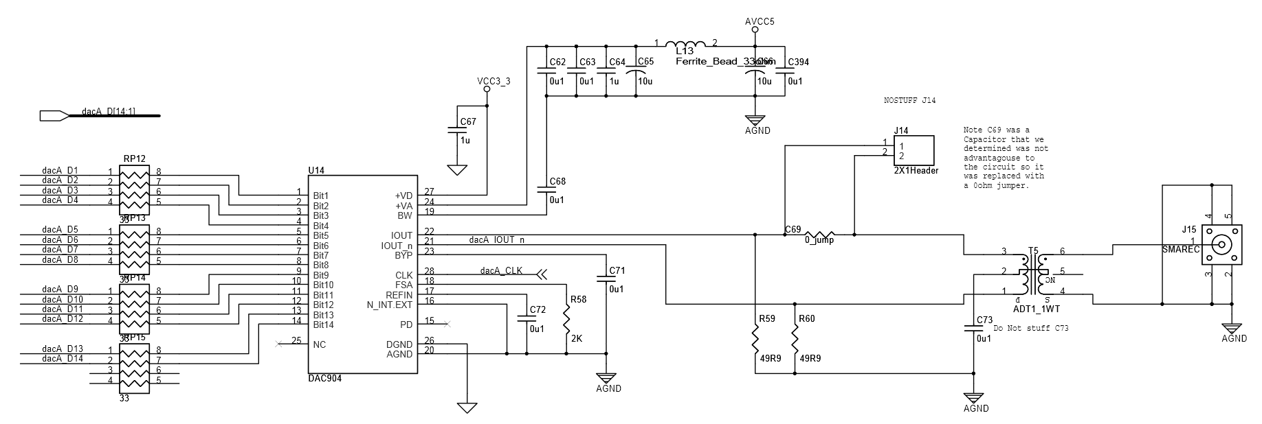
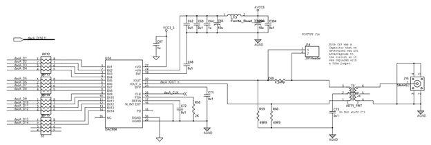
> I think that I just supply the clock on pin28 of DAC904, and input the
> 14bit digital data
That far you are right...

> and I will have the analog signal on pin 22 of DAC904.
This is correct, but you must measure a current, not a voltage. To get
an output voltage you must desolder the jumper resistor C69... ;-)
thank you very much. the schematic you gave is same in the board I have.
So, in the jumper J14 in the board, I must connect pin 1 to pin 2 to get
output voltage, right?

I want to give a special thank to you again,
> So, in the jumper J14 in the board, I must connect pin 1 to pin 2 to get
> output voltage, right?
No, those two pins are already connected by C69!
You must disconnect them by unsoldering C69 (which is a zero Ohm
bridge actually)...
I understand, I must remove C69 to get the voltage output, right? ^^
it's not possible

I just want to show to spectrum of signal via DMA port (J15 in the
schematic). I have a DMA connecter to connect the signal from J15 to
spectrum analyzer. However, I dont know how to check the signal at DMA
port (I tried to use VOM to get the voltage at J15 but I have 0V out). I
must remove the C69? any other way?
> However, I dont know how to check the signal at DMA port
> (I tried to use VOM to get the voltage at J15 but I have 0V out)
Of course you cannot transmit a DC through a transformer like T5.

> I must remove the C69?
No, you must hand out all the necessary information. Previously you
wrote about a voltage at the DAC ooutput pin, now you want to measure
something completely different...

> any other way?
You must supply an AC signal to the transformes input. So simply toggle
the DAC input signal with every clock between any value and 0. Or
implement a 14 bit counter and count up every clock cycle. Or implement
a DDFS (ok, just little joke for now... ;-)
Lothar Miller wrote:

> Of course you cannot transmit a DC through a transformer like T5.
> yes I see, I already tried to get the AC via oscilloscope. But there is no
signal.
>>
> No, you must hand out all the necessary information. Previously you
> wrote about a voltage at the DAC ooutput pin, now you want to measure
> something completely different...
> I think more what you said
>> any other way?
> You must supply an AC signal to the transformes input. So simply toggle
> the DAC input signal with every clock between any value and 0. Or
> implement a 14 bit counter and count up every clock cycle. Or implement
> a DDFS (ok, just little joke for now... ;-)


I tried to output the counter 14bit into the input of DAC. and I use
oscilloscope to get the AC voltage at the DMA J15. The result I got is
always 0V AC. I dont know why. That is the reason I try to get the
output of DAC before the transformer to check whether the DAC is broke
or not.

I wonder is there any requirement of DAC input clock? it must be higher
than 10M or something like that? the maximum clock of DAC is about 150
MSPS,it means it will operate at high clock (maximum 150 Mhz). But I
dont know where is the minimum limit? can you guess ? anyway, I will try
to check the counter again tomorrow by oscilloscope.

thank you
The lower frequency limit is given bei the transformer, not the DAC.
> I tried to output the counter 14bit into the input of DAC. and I use
> oscilloscope to get the AC voltage at the DMA J15.
Can you see the counting pattern on the input pins of the DAC?
Do you see the clock on the clock pin of the DAC?
Lothar Miller wrote:
>> I tried to output the counter 14bit into the input of DAC. and I use
>> oscilloscope to get the AC voltage at the DMA J15.
> Can you see the counting pattern on the input pins of the DAC?
> Do you see the clock on the clock pin of the DAC?
 Hi Lothar Miller,

Yep.. I check the digital input signal on the DAC input pins and the
clock at the clock_pin on DAC. They are absolutely presented. I tried to
change the counter clock from 1Hz to 1Mhz (also change the clock of DAC
according to the counter clock). after that I used the oscilloscope to
observe the analog output via DMA connector. Tomorrow, I will take some
pictures and post here. pls follow and help me.

Thanks you,
> I tried to change the counter clock from 1Hz to 1Mhz (also change the
> clock of DAC according to the counter clock).
Of course 1 Hz counting frequnecy is MUCH too low!!!
Thats DC for the transformer!

And even 1 MHz will also be MUCH too low and result in a output
frequency of 61 Hz. Thats almost DC for the transformer!

This transformer is specified for 400 kHz to 900 Mhz with a loss of 3db:
http://217.34.103.131/pdfs/ADT1-1WT.pdf
Now image what your loss will be with a frequency 4 decades lower than
the lowest frequency specified...   :-o
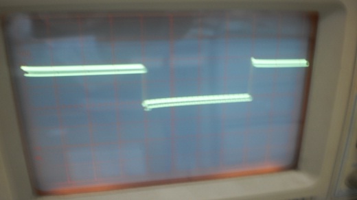
1.  The clock at pin 28 of DAC 904 (U14 on stratixII) :  around 1Mhz
 figure (1)

2.  The LSB input bit input[13]: around 1MHz
 (figure (2)
3.  The input digital bit: input [12] (just for checking the output of
couter, also input of DAC 14bit): around 0.5 MHz
 (figure (3)

From (1) (2) and (3) => DAC clock  and digital input already PRESENTED.

4.  Output  analog (AC mode).

(figure (4)

The way I measure (I measured output analog signal at DMA port (J15) in
the stratix ii board as shown below:

figure (5)


In previous posts, you said that the output of DAC 904 is Current (see
the ficture bellow), so I must measure the current. However, in the
schematic of the board. I see the registers R59 and R60 connected with
IOUT and IOUT_n port of DAC 904. So it already converted to VOLTAGE? Am
I right? Please help me. Thank you very much
figure (6)

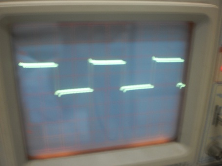
this is the figures, I am sorry for posting it after the test
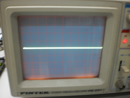

this is more 3 pictures...thank you
Attached files:
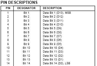
> 2.  The LSB input bit input[13]: around 1MHz
And what is the DACs MSB input frequency (Pin 1 at DAC)?

> 2.  The LSB input bit input[13]: around 1MHz
> 3.  The input digital bit: input [12]: around 0.5 MHz
Pls add the pin numbers you measured at. Its a real crude and strange
numbering of bits within this datasheet: bit 1 is MSB and bit 14 is LSB.
Never seen such an order before...  :-o
Thank for your opinion,

However, in the reference manual of Stratix II board. They NOTE that:
"The Texas Instruments (TI) naming conventions differ from those of
Altera
Corporation. The TI data sheet for the DAC 904 D/A converter lists bit 1
as the most significant bit (MSB) and bit 14 as the least significant
bit (LSB)."

But I will map data into the pins like datasheet of DAC 904. and try to
increase the frequency of DAC input clock. And I will tell you

thank you
> But I will map data into the pins like datasheet of DAC 904.
You just have to measure directly at the pins to be sure...
The only interesting frequency with your counter is that at the MSB pin
1 of the DAC. This frequency must be higher than 400kHz due to the
transformers frqeuncy response.
thank you, I will try tomorrow.
anyway, I want to confirm one more thing. You said that the you said
that the output of DAC 904 is Current, so I must measure the current.
However, in the schematic you gave me. I see the registers R59 and R60
connected with IOUT and IOUT_n port of DAC 904. So it already converted
to VOLTAGE? I think so. Therefore, I am not clear why you said that it
is the current output
Lothar Miller wrote:
>> But I will map data into the pins like datasheet of DAC 904.
> You just have to measure directly at the pins to be sure...
Today I measure again, and the pins of DAC 904 is mapped correctly.
> The only interesting frequency with your counter is that at the MSB pin
> 1 of the DAC. This frequency must be higher than 400kHz due to the
> transformers frqeuncy response.

I dont think this requires for MSB bit. assume that the frequency of MSB
must be higher than 400kHz as you said. So, the clock for the counter
must higher than 6.5GHz. It too high. the maximum clock of the board is
just 100Mhz. you can check for me again?
I just think that this require for the input of DAC. So LSB (not MSB)
must change with minimum frequency of 400KHz. I try to change the
frequency of LSB to 1Mhz. but it's still no output signal.

Do you have any board FPGA Stratix? I will code and send the code for
you to load on the board. I want to make sure that my DAC on-board is
not broken.
> However, in the schematic you gave me. I see the registers R59 and R60
> connected with IOUT and IOUT_n port of DAC 904. So it already converted
> to VOLTAGE? I think so.
Not until you desolder the jumper C69. Because the current thats coming
out of the pin 22 (IOUT) has its way through the transformer to pin 21
(IOUT_n), so theres no current left for a defined voltage drop over
R59 and/or R60.

> I just think that this require for the input of DAC. So LSB (not MSB)
> must change with minimum frequency of 400KHz.
Of course, but then you will have only 1/(2^14) of the maximuam swing of
the output signal. Ich you are able to measure such very small
signals, then that will be ok. But according to your photos you will not
see the faint signal on the skope in between the noise...

> So, the clock for the counter must higher than 6.5GHz. It too high.
Good theoretical calculation. The problem is, that you are stuck with
your 14 bit counter and its bit order.
So try that one: instead of counting try to toggle the complete 14
bits form all 1's to all 0's and back and so on with the 100MHz clock.
Then all the bits will make a 50MHz signal and the output signal must
make a complete 50MHz swing.

> Do you have any board FPGA Stratix?
No. But the problem ist farily clear to me: I would get the thing
running in half an hour unless the DAC is already damaged...
Today, I try to test the code for stratix board EP1S25F7. The DAC 904 in
this board is OK. there is a little different is that the output of this
board is not built in the transformer. So, I need the schematic of DAC
904E in this board, can you upload it for me? I did not found the
schematic as you did as in your previous post. I need to compare two
schematics of DAC on two boards.
Thank you very much
Dear Lothar Miller,

I found the problems...I dont know... the problem is...no problem. I did
as you said... just output 14bit of 0 and 14bit of 1. the signal output
in the stratix II board is changed with the frequency of input sequence.

However, in the Stratix I (I test the code in two kinds of Stratix
board), I can easily observe the output signal on oscilloscope in the
same condition. But in the Stratix II board, I cant see any signal like
in the stratix I board...

Anyway, I learned a lot from you.

Want to give a special thank to you.

if you dont mind, send me your email. I want to know some other private
information.

my email is nguyentu.hcmuns@gmail.com
thanks
> However, in the Stratix I (I test the code in two kinds of Stratix
> board), I can easily observe the output signal on oscilloscope in the
> same condition. But in the Stratix II board, I cant see any signal like
> in the stratix I board...
Maybe theres an additional difference in the schematics.

> if you dont mind, send me your email.
You will find my email on the web, but I prefer not to be contacted
with private questions.

> Want to give a special thank to you.
De nada.
Please log in before posting. Registration is free and takes only a minute.
Existing account
Do you have a Google/GoogleMail account? No registration required!
Log in with Google account
Log in with Google account
No account? Register here.