LPC2148 I2C I2xSCH timing problem

Guest #1666026
Rate this post
useful
not useful
Im using in my project a LPC2148 controller and have a question 
concerning I2C timing. Everything works quite well but when I proofed 
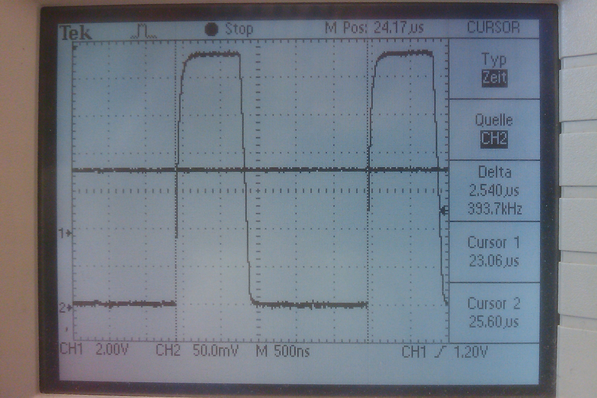
the timing of the I2C I discovered that the high time of the clock is 
wrong. With I2xSCL/H you can adjust the high and low time (duty cycle) 
of the clock. The value says how many clock cycles are used for 
high/low. My PCLK runs at 60MHz (I proofed that with a PWM Output, the 
frequenzy/duty cycle was exact the expected value). If I set I2xSCL/H to 
75 the expected I2C data rate should be 400kHz. In reality it is about 
384kHz because the high time of the clock is about 110ns too long 
(1.36us instead of 1.25us). The low time fits exactly (1.25us). This 
problem occurs on both I2C busses. Do you have any suggestion/experience 
on this topic? Thank you for some help.
Guest #1666123
Rate this post
useful
not useful
Thanks for your answer. I measured the on time with an 100MHz 1GS/s 
Oscilloscope. The on time is the time from the beginning of the rising 
edge until the beginning of the falling edge. This time is too long. 
That means the falling edge should start earlier. There is always the 
same time offset of about 110ns (about 7 cycles@60MHz) on the on time 
indepent of the value in I2xSCH. So the effect becomes more visible at 
higher frequencies. The low time (beginning of falling edge until 
beginning of rising edge) fits exactly. To eliminate side effects there 
is no slave on the bus (only pullups) and I write a random Byte on the 
bus. During this Byte-write I measure the clock timing on the bus.
Guest #1666225
Rate this post
useful
not useful
could it be that the maximum i2c frequency is limited to ~375kHz when 
using 60MHz peripheral clock?
table 143 at page 147 on doc UM10139 would suggest so.
sry, that's all i got...

edit: or maybe not.
there's some errata sheet on the lpc2148 that reads an erroneous 
behavior on pulse time generation for the SSP1 module.
maybe, this error occours on the i2c module also and is just not 
documented yet.
you could test that by monitoring later pulses after the first 4.

errata sheet:
1
SSP.1Initial data bits/clocks of the SSP transmission are shorter
2
than subsequent pulses at higher frequencies
3
Introduction: The SSP is a Synchronous Serial Port (SSP) controller
4
capable of operation on a SPI, 4-wire SSI or a Microwire bus. The SSP
5
can operate at a maximum speed of 30MHz and it referred to as SPI1 in
6
the device documentation.
7
Problem:           At high SSP frequencies, it is found that the first
8
four pulses are shorter than the subsequent pulses.
9
[...]
10
Work-around: None.
Guest #1666311
Rate this post
useful
not useful
Thanks for your answer again. I dont´t think that I2C speed on that 
controller is limited to 375kHz. At this point the datasheet can be 
missunderstood. It says you must ensure that the I2C speed stays within 
0 to 400kHz and that each value of I2xSCH/L must be equal or bigger than 
4. So I think the 400 kHz refer to fast I2C mode spezification and the 
LPC can do faster. I used 2MHz with my BMP085 pressure Sensor without 
any problem. Furthermore the problem occurs at all frequencies. During 
one Byte transfer all 9 clock pulses are of the same length (but too 
long). I wrote to nxp technical support. Maybe they know an answer.
Guest #1666842
Rate this post
useful
not useful
Now I got an answer:

"Try with a smaller value for the pull-up resistors. Slow clock edges 
cause extended pulse length."

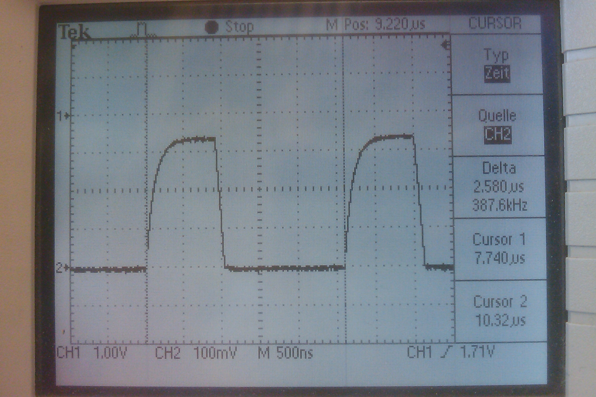
I tried this and it worked. I reduced the pullup resistors from 4k7 to 
1k2 and the I2C data rate changed (with the same settings in I2xSCH/L) 
from about 384kHz to 396kHz which is very close to 400kHz. I also tried 
800 Ohm and got 398kHz. So there is a dependence of the pullup resistor 
and the pulse length.
Guest #4919413
Rate this post
useful
not useful
i'm facing problem with i2c1 in lpc2148. i'm connected the sensor to the 
i2c0 it's working fine, but with the connection same code but changed 
the registers instead of the i2c0 replaced the the i2c1. then it's 
giving 0xF8 at start bit it means no connection like...
and also another thing i did just added pull up resistors even at the 
time also not worked. it cleared the start bit problem and after that 
another problem is sending the slave address there ack, and also it's 
giving an error that's regarding bus error.
please............. give me better solution for this almost i worked on 
2 weeks even there is no small change.
Guest #6197293
Rate this post
useful
not useful
At this point the datasheet can be missunderstood. It says you must 
ensure that the I2C speed stays within 0 to 400kHz and that each value 
of I2xSCH/L must be equal or bigger than 4.

So I think the 400 kHz refer to fast I2C mode spezification and the
LPC can do faster. I used 2MHz with https://www.mywegmansconnect.one my 
BMP085 pressure Sensor without
any problem. Furthermore the problem occurs at all frequencies. During
one Byte transfer all 9 clock pulses are of the same length (but too
long). I wrote to nxp technical support. Maybe they know an answer.
(Company: adbesds) #6815249
Rate this post
useful
not useful
ChangeBloodElf wrote:
> At this point the datasheet can be missunderstood. It says you must
> ensure that the I2C speed stays within 0 to 400kHz and that each value
> of I2xSCH/L must be equal or bigger than 4.
>
> So I think the 400 kHz refer to fast I2C mode spezification and the
> LPC can do faster. I used 2MHz with https://allaboutwegmans.jimdosite.com my
> BMP085 pressure Sensor without
> any problem. Furthermore the problem occurs at all frequencies. During
> one Byte transfer all 9 clock pulses are of the same length (but too
> long). I wrote to nxp technical support. Maybe they know an answer.

 I2C bus is a Byte Oriented bus. Only a byte can be transferred at a 
time. Communication(Write to & Read from) is always initiated by a 
Master.
Thanks
(Company: Webcorewin) #6852853
Rate this post
useful
not useful
I added more information above. Another board works all the time, this 
one works for around 10 or so read/writes and then the micro throws a 
bus error interrupt. Pull-ups are 4.75k to 3.3 V.It looks like from the 
scope shot that SDA went low a little too soon but it's hard to tell how 
much time difference there may be from the image, and the clock low 
period after that looks shorter than others. Not sure about the clock, 
maybe it's within tolerance, but the SDA going low could qualify as a 
start condition (at a time when it may not be valid). You might try 
comparing the equivalent waveforms from the working board to this one to 
see if it's also having marginal timing but just happens to work.

Reply

Please log in before posting.

or

Log in with Google account

Registration is free and takes only a minute.

Register now