sich bequem durch Angabe einer Oktalzahl einstellen lassen (z. B. entspricht "751" dem Bitmuster "111 101 001" oder "rwxr-x--x" in der üblichen Zugriffsrecht-Darstellung.) . Umrechnung. Viele Taschenrechner können die Zahlensysteme umrechnen, so auch der Windows-Taschenrechner oder der UNIX-Taschenrechner
Optoelektronik, HF B: div.THT: 74LS/HCT/TL072/NE5532/MC33078, BF245B, BAT42, SIL Reed Relais SMD: J111, BCP53-16, TLC272, TLC372, DIR1703, LP2985 1,8V, div. L/C/R Chipbauteile... 11 Simon 81xxx 02.06.2025 10.06.2025 Hermes: 02161165005342 15,7kg S: Bauteile, v. A. THT B: THT/SMD, ICs, Stecker, Buchsen
Optoelektronik, HF B: div.THT: 74LS/HCT/TL072/NE5532/MC33078, BF245B, BAT42, SIL Reed Relais SMD: J111, BCP53-16, TLC272, TLC372, DIR1703, LP2985 1,8V, div. L/C/R Chipbauteile... ENDE Runde VIII =Ergänzende Informationen= In diesem Abschnitt können Benutzer Links zu Datenblättern oder auch Schaltpläne
eine Richtung, -1 und 3 in die andere Richtung dar. Deren Bitmuster sind 0b0…001, 0b1…101 bzw. 0b1…111, 0b0…011. Damit wird klar, dass man Bit 0 (diff & 1) als Kennzeichen heranziehen kann, dass sich in diesem Schritt überhaupt etwas geändert hat, und Bit 1 (diff & 2) als Kennzeichen für die Richtung
Clare) LOC117 Single Linear Optocoupler IXYS (Clare) LOC112 Single Linear Optocoupler IXYS (Clare) LOC111 Single Linear Optocoupler IXYS (Clare) LOC110 Single Linear Optocoupler IXYS (Clare) LIA120 Optically Isolated Linear Error Amplifier IXYS (Clare) Applikationshinweis zur LOC-Serie linearer Optokoppler
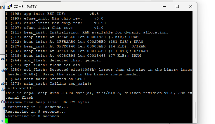
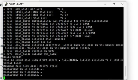
heap_init: At 3FFE0440 len 00003AE0 (14 KiB): D/IRAM
I (232) heap_init: At 3FFE4350 len 0001BCB0 (111 KiB): D/IRAM
I (238) heap_init: At 4008CB98 len 00013468 (77 KiB): IRAM
I (244) spi_flash: detected chip: generic
I (247) spi_flash: flash io: dio
I (250) spi_flash: Detected size (4096k) larger than
For example, addition can be performed as: This will first load the value 222 into register r0, load 111 into r1, and finally add r0 and r1 and store the result (i.e. 333) in r2. The operand for the result is (almost) always put on the left, while the input operand(s) follow on the right. You can also
b10: begin // DATA_BITS state receivedData[bitIdx] <= in; // Collecting data bits if (bitIdx == 3'b111) begin bitIdx <= 3'b0; out <= receivedData; // Store received byte state <= 2'b11; // Transition to STOP_BIT state end else begin bitIdx <= bitIdx + 3'b1; end end 2'b11: begin // STOP_BIT state if (
DATA_BITS: begin // Send 8 data bits out <= data[bitIdx]; done <= 1'b0; busy <= 1'b1; if (bitIdx == 3'b111) begin bitIdx <= 3'b0; state <= STOP_BIT; end else begin bitIdx <= bitIdx + 1'b1; end end STOP_BIT: begin // Send out Stop bit (high) out <= 1'b1; // Send stop bit state <= DONE; end DONE: begin if
IDE Portable\AVRxDB\arduino-1.8.19\portable\sketchbook\libraries\MyFramControl\src/MyFramControl.h:111:18: warning: use of 'auto' in parameter declaration only available with -fconcepts void readTo (auto(&otherObj)) { fram.read(initObjAddr, otherObj); } ^~~~ C:\Arduino IDE Portable\AVRxDB\arduino-1.8.19
to bus a The return_out output will only be modified when change has a value different from 3'b111. If change is equal to 3'b100, then the return_out output will be equal to the bus formed by the least significant bits of a and b. If change is equal to 3'b001, then the return_out output will
component* of your testbench. And the testbench manages the interconnets between the ReadFile and lab111 *components*.
testbenches should not have entities, i created a new testbench, instantiated both the ReadFile and Lab111 as components, make the necessary port and generic maps & was finally able to load the data into the testbench. Thanks again. Best of Regards, Zahid.
Low Pass Filter library IEEE; use IEEE.STD_LOGIC_1164.ALL; USE ieee.std_logic_arith.all; entity lab111 is Port ( clk : in STD_LOGIC; din : in STD_LOGIC_VECTOR (15 downto 0); dout : out STD_LOGIC_VECTOR (15 downto 0)); end lab111; architecture rtl of lab111 is type tdelay is array (7 downto 0) of std_logic_vector
-- 000 0 turn off 001 0 turn on 001 1 cooling 010 1 fan 011 1 demist 100 1 ??? 101 1 --- 110 1 --- 111 1 --- A = Automatic-Programm A ---------- 0 off 1 on t = Timer t x y ---------- 1 1 0 Timer 1 1 0 1 Timer 2 To control the air con via IRSND, the following functions can be used: LGAIR Protocol. The
Mode, can be combined with temperature 000=Mode 0 001=Mode 2 010=???? 011=Mode 1 100=Mode 3 101=??? 111=??? tttt: Temperature: 0000=used by OFF command 0001=???? 0010=???? 0011=18°C 0100=19°C 0101=20°C 0110=21°C 0111=22°C 1000=23°C 1001=24°C 1010=25°C 1011=26°C 1011=27°C 1100=28°C 1101=29°C 1111=30°C
Anschließend wir der Wert aus r16 in das DDRB geladen, dazu dient der Befehl out [A TMEL INSTRUCTION SET, S.111]. Das DDRB hat die Adresse 0x04 [Atmel Datenblatt 2009, Tabelle S.426], so daß sich jetzt folgendes ergibt: 1 Allerdings vgl. die Anweisung sbi [ATMEL INSTRUCTION SET, S. 128] 2 Einführung in das physical
b and c connected at the bottom of the MUX? The left input is b, then a and right is c. So 000 ... 111 is a combination of b, a, c. In VHDL it would be: signal sel := std_logic_vector(2 downto 0); begin sel <= b & a & c; with sel select y <= a and b when "000", c when "001
3'b111: y = a ^ b; endcase end assign sel = b & a & c;
you have to give every value the correct 4bit. If the int is 9 (1001) so the Segments are all on (111 1111). How is it decided what time is the alarm time? Does the current time just count up from 0 to 9?
I2S-Datensignals aufgenommen mit einem FPGA-basierten DIY-Tester unter Nutzung eines 6-Bit-Musters (000.000 -> 111.111) = 64 Kombinationen und 4 überlagerten Durchläufen. Nutzfrequenz 49152 MHz (768 kHz Audio), Abtastung x 4, Plattform: Terrasic DE-115 mit Cyclone IV-FPGA. Am Ende der Leitung ist das Auge noch gerade
needs 22 bits. The last 3 bits contain the target address. In dual modulus mode this bits have to be 111. N/A divider in binary: 0010 1010 0011 1010 1101 1110. First and last bit is always 0. Bits 2...8 contain the value of divider A and bits 9...23 that of divider N. Divider A = 42 Divider
bits. The > last 3 bits contain the target address. In dual modulus mode this bits > have to be 111. > > N/A divider in binary: 0010 1010 0011 1010 1101 1110. > > First and last bit is always 0. Bits 2...8 contain the value of divider > A and bits 9...23 that of divider N. > > Divider A
routing tables so that no more route records willbe sent to the aggregator. Digi XBee®3Zigbee®RF Module 111 Transmission, addressing, and routing Encrypted transmissions Disable route records If an aggregator collects route records from the nodes of the network andno longer needs route records sent (which
Operationen. Beispielsweise kann das Hinzufügen wie folgt durchgeführt werden: ldr r0 = 222 ldr r1 = 111 addiere r2, r0, r1 Dies lädt zuerst den Wert 222 in das Register r0, lädt 111 in r1 und addiert schließlich r0 und r1 und speichert das Ergebnis (d. H. 333) in r2. Der Operand für das Ergebnis steht
instructions for mathematical operations. For example, addition can be performed as: ldr r0, =222 ldr r1, =111 add r2, r0, r1 This will first load the value 222 into register r0, load 111 into r1, and finally add r0 and r1 and store the result (i.e. 333) in r2. The operand for the result is (almost) always put
 Image
Image
 Image
Image
 Image
Image