-
Thread
STM32L1xxx µC displaying memory contents
first of all would like to greet everyone from my side. I am working as an intern and working with STM32L152 EVAL board. I am supposed to take the digital values from the ADC converter from an analog input and save them for the first run. In the second run I have to save the second values and compare
-
Thread
STM32 & ADC AD7699: fading SPI MISO level
Hey guys, I'm facing a problem working with an STM32F103RET6 and an ADC AD7699 (datasheet: http://www.analog.com/static/imported-files/data_sheets/AD7699.pdf). I thought maybe some of you might have similar experiences and could give me a hint. As
-
Thread
STM32F407 TIM5 external Clock/ ChibiOS
Hello, i want to configure the Timer 5 with an external Clock (Button). This is my code, but it doesn't work correct: GPIOA->MODER |= GPIO_MODER_MODER0_1; // Enable AF mode for A0 GPIOA->AFRL = (GPIOA->AFRL & 0xFFFFFFF0) | 0b0010; // Select AF2 for A0 TIM3/4/5) RCC->APB1ENR |= RCC_APB1ENR_TIM5EN; // Enable TIM5 clock TIM5->CCMR1 |= TIM_CCMR1_CC1S_0; // Input mode, map TI1 to IC1 TIM5->CCER &= ~(TIM_CCER_CC1P | TIM_CCER_CC1NP); // CC1P and CC1NP = 0 for rising edge //TIM5->SMCR |= TIM_SMCR_SMS; // External clock mode 1 TIM5->SMCR |= TIM_SMCR_ECE;
-
Thread
yagarto example project for STM32F100C4 chip
Hello, I'm new user of the yagarto tool-chain. The example project for STM32F103 works well for me. I'm going to move to simpler target chip STM32F100C4. It should be the Low density Value Line device (STM32F10X_LD_VL). I'm not sure how to setup-up project or how to modify linker script and start-up code for that chip. Please can someone send me a example project for STM32F100C4 for yagarto or any advice how to do it please?
-
Thread
STM32F429 DMA2D bilinear bitmap resize
Hello everyone, I wrote a simple but powerful DMA2D app to resize a bitmap using bilinear interpolation using very low CPU resource. A demo video is on https://www.youtube.com/watch?v=TgTxBIYUuVM and the source code is available on http://www.mediafire.com/download/w25kovq8umnmou0/DMA2D_bilinear_resize.rar Enjoy !!!
-
Article
Datei:STM32 nucleo F411RE Rückseite Brücken.jpg
STM32_nucleo_F411RE Board, Rückseite mit Brücken
-
Article
Datei:STM32F103C8T6.png
STM32F103C8T6 Mini Development Board
-
Article
Datei:Debugging STM32F103 USB InitPacket.png
Anzeige des ersten Pakets vom Host beim Debugging einer USB-Anwendung auf STM32F103. Autor: Niklas Gürtler Lizenz: CC BY 4.0
-
 Image
Image
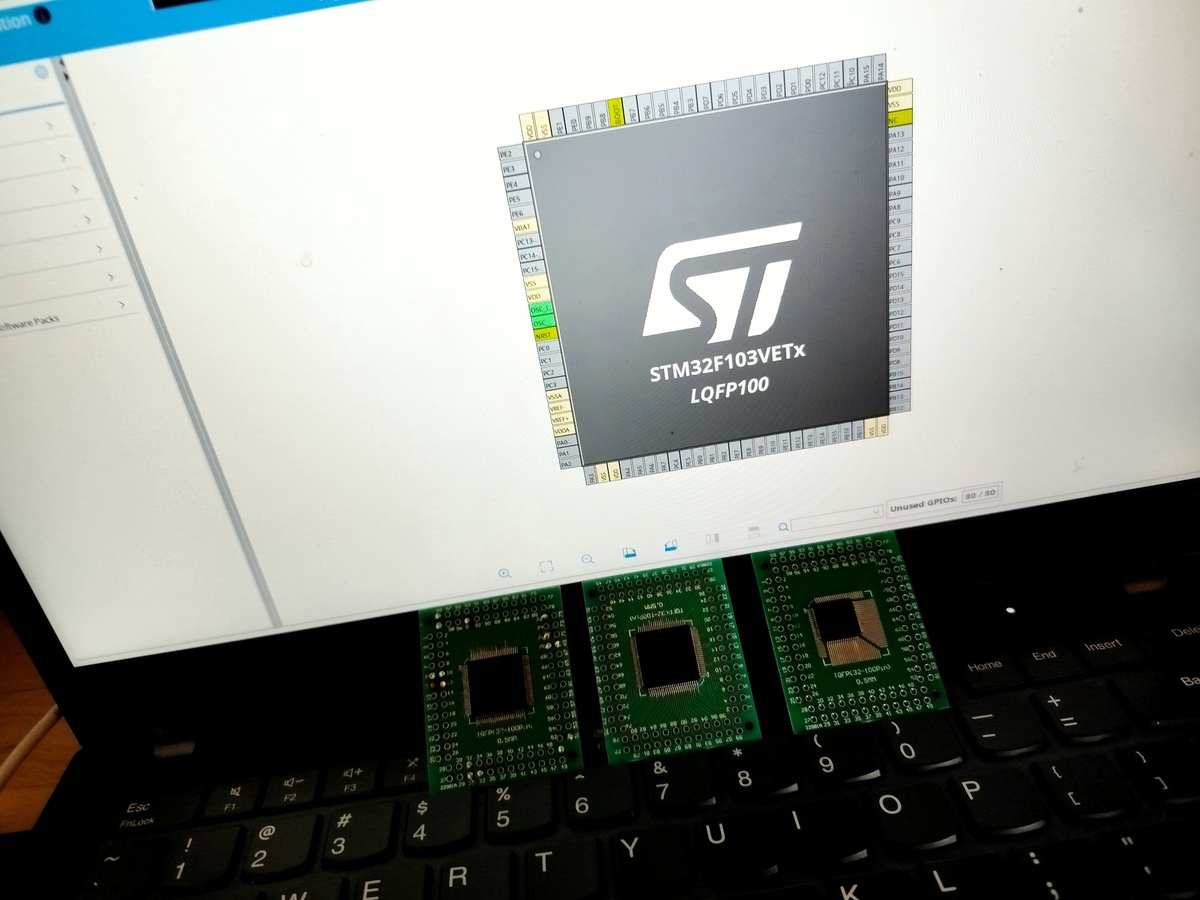
Laptop mit STM32F103VETX Chip-Abbildung und drei Mikrocontrollern
STM32F103VETX LQFP100
-
Article
Datei:Wordclock24h-Web-Update-Flash-STM32.png
Version 2.8.0
-
Article
Datei:Stm32f103c8t6 blinky.bin
blinky on PC13
-
Article
Datei:STM32F103-Bootloader-2.6.0.png
Ab Version 2.6.0
-
Article
Datei:Timer2 STM32F103 1.0.rar
(Beispiel Projekt für die verwendung von Timer 2 mit Interrupt)
-
Thread
STM32F1xx: Injected simultanous ADC doesn't work
with injected ADC1 and ADC2 triggered by Timer1 Capture Compare Channel 4. See chapter 5.1 of the STM manual UM1052: https://www.st.com/content/ccc/resource/technical/document/user_manual/5e/5e/d2/cb/07/35/45/a6/CD00298474.pdf/files/CD00298474.pdf/jcr:content/translations/en.CD00298474.pdf The interrupt
callback, it works. here are two screenshots of the relevant registers at runtime. http://www.stm32duino.com/download/file.php?id=3190&sid=68aec5aeb5f8c2092a3f0dfd85a63b81 http://www.stm32duino.com/download/file.php?id=3190&sid=68aec5aeb5f8c2092a3f0dfd85a63b81 Any idea what's going wrong?
-
Thread
STM32F407 software trigger a one pulse timer using HAL
Hello, I have a question about STM32F407. I was wondering how to software trigger (not external trigger) a "one pulse" timer, using HAL library? Thanks for the help.
Masoud B. wrote in post #6778090: > Hello, > I have a question about STM32F407. > I was wondering how to software trigger (not external trigger) a "one > pulse" timer, using HAL library? > Thanks for the help. I have a question about STM32F407. I'm wondering how to
-
Thread
STM32F4 Discovery Board: Functions calling in Atollic TrueStudio
some explanations about few things. I hope somebody could give me some. So! I'm working with the STM32F4 Discovery Board and using the IDE Atollic TrueStudio. I wrote a code for calculating the distance with the distance sensor HC-SR04. My code is working fine when I'm writting it in successively
-
Thread
USART1 issue with a STM32F030R8 Nucleo Board
MAIN_H /* Includes ------------------------------------------------------------------*/ #include "stm32f0xx.h" #include "stm32f0xx_rcc.h" #include "stm32f0xx_it.h" #include "stm32f0xx_gpio.h" #include "stm32f0xx_rtc.h" #include "stm32f0xx_nucleo.h" #include "stm32f0xx_conf.h" #include "stm32f0xx_usart.h
Hey, Benoit wrote in post #3658640: > GPIO_PinAFConfig(GPIOA, GPIO_Pin_2, GPIO_AF_0); STM32F030R8 hasn't mapped USART1 on PA2, please read the datasheet page 31. USART1 is available on STM32F030x6 and STM32F030x4 devices only. Benoit wrote in post #3658640: > GPIO_PinAFConfig(GPIOA,
-
Thread
STM32H7 real-time data tracing via SWD not working
oscilloscope (No edges detected) -Reading STLINK Jumpers with oscilloscope (Edges detected) -Other IDEs SW4STM32 (No success) -Serial wire viewer of STLINK (nothing shown) -Tried debugger and builder / optimization settings. (Still no success) See screenshots for detailed description and the configurations
real-time* trace data. But anyway, look there: https://community.st.com/s/question/0D50X00009XkhURSAZ/stm32h7-swo-printf-not-working
-
Thread
Designing a Digital Tuner for Electric Guitars by Using STM32F4
from 200mV up to 1V of peak, with also negative peaks (of the same magnitude). I have to use the STM32F4 (Discovery Board:http://www.kynix.com/Parts/3597871/STM32F4-GAME.html), so I need a very simple circuit that drives the On-Board 12-bit ADC, that takes, as inputs, signals with voltage between 0
Ada L. wrote in post #4923185: > STM32F4 provides some voltage sources (5v or 3v). Shall I use these > sources The board supplies the voltages, not the STM32! And yes: you can use them for your design, as it will draw only a few mA.
-
Article
Datei:STM32 Nucleo F411RE Rückseite ST-Link.jpg
ST Link Rückseite
-
Article
Datei:STM32 nucleo F411RE Bestückungsseite ST-Link.jpg
ST Link Bestückungsseite
-
Thread
STM32H7 bank swap break at address 0x81006fe
I trying to do a bank swap with the ST32 H743ZI2. I wasted much of time to fix it but i didnt get it. Maybe because im new in STM32 controllers. I copied the bank swap code from STM32CubeH7 Firmware Examples and did a few modifications regarding
configuration in CubeMX. I did them because i want to implicate the code in a excisting project without the stm32h7xx_nucleo headers. Following the Code for Bank1: [c] HAL_FLASH_Unlock(); HAL_FLASH_OB_Unlock(); while (1) { /* Wait for BUTTON_USER is released */ if (HAL_GPIO_ReadPin(GPIOC
-
Thread
STM32F0 Discovery Port C Pin 1 and Pin 2 problem
Hello Folks, I tear my hair out over this. I have a STM32F0 Discovery board here and i would like to get all 16 bits of PORTC high. Most of the pins do what i expect them to do, but PC1 and PC2 dont. They stay low out of what ever reason. I am a bloody newbie
I am chewing on this problem already since a week and ready to give up on it. [c] #include "stm32f0xx.h" #include "stm32f0xx_rcc.h" #include <stm32f0xx_conf.h> #include "stm32f0xx_gpio.h" #include "diag/Trace.h" //#include <stdio.h> int main() { GPIO_InitTypeDef GPIO_InitDef;
-
Thread
_sbrk error , how to solve for STM32F4 ?
I am trying to compile a C program for STM32F4 microcontroller with yagarto I have run into following error [c]c:/olimexods/yagarto/bin/../lib/gcc/arm-none-eabi/4.5.1/../../../../arm-none-eabi/lib\libg.a(lib_a-sbrkr.o): In function `_
-
Thread
DHT22 Sensor readings unrealisitc with STM32F407 uC
First of all i want to say hello I have a problem with my DHT22 temperature and humidity sensor. The start signal is fine, the sensor response signal is fine, the bits that the sensor sends me are fine my problem is how can i read out the data that the sensor sends me because my values are 2700 for humidity and between 4500 and 5800 for temperature. As you will see in the attatched file, i hope it works this is my first post, i have tried it using a for loop and after the sensor pulls the data line to 0 for the 50us low voltage that comes before every bit, i will put the datasheet down below,
-
Thread
[Solved] STM32F0 Discovery Board: Connect faild, check config and cable connection
Hi I bougth the Stm32F0 Discovery to get into microcontrollers. I have only knowlegth about c# and java programming. I followed this tutorial (video http://www.youtube.com/watch?v=nP6TR6NAZTQ) Downlaoding coocox
/CoIDE/flash/STM32F05xx_64.elf" Error: Connect failed, check config and cable connection Program Download Failed ! I have no cloue what to change. Can anyone give me a hint? Do I Have to know anything else
-
Thread
STM32F1xx EXTI problem to trigger interrupt by SWIER
Hallo, i have the following problem to solve: an interrupt should be triggered when the frame-signal of a SPI-interface changes from 0 to 1. If, at the time of enabling this interrupt, the frame-signal is already high, the interrupt should be triggered by software instead of the rising edge. I am using int-structures representing the register-bits of EXTI and other peripherals mapped to the according places within the bit-banding-area of the micro. These are name XXXbbbits. I am also using bit-structures which are representing the structures of their according registers to manipulate two
-
Thread
STM32 GDB / OpenOCD Commands and Initialization for Flash and Ram Debugging
initializing OpenOCD I used the following command in Eclipse (The board config file references the stm32 mcu and was found in the OpenOCD installation as an example): "openocd -f interface/olimex-arm-usb-ocd-h.cfg -f board/stm32f10x_128k_eval.cfg". When I run this within Eclipse everything appears
jim, take a look at the STM32F... example at the yagarto site how to setup a makefile for RAM and FLASH target. try to understand the example (memory maps) before u proceed. look at the jlink command scripts and look into the
-
Thread
need help with debugging Cortex M3 (STM32) using Eclipse, YAGARTO and J-Link
deasserted during "monitor reset" the clock will be the default clock after reset as mentioned see STM32 reference-guide.
with the new libusb-win32 V1.2.1.0. I compiled and ran OpenOCD with the current version of Cygwin (1.7.5) on XP. My JLink firmware is V6. In the past, I used to try OpenOCD/JLink/STM32/XP with several releases and RCs,
-
Thread
STM32F03x - SPI via DMA -missing CLK on MISO
Hello, I have got a Problem with an STM32F030 Device, using SPI via DMA. I try to set and load Data from HC595 and HC165 chips via SPI. SPI is configure in Full duplex mode and prescaled down to a frequency of 8Khz. MOSI and SLK are
-
Article
Datei:ESP-12F-an-WC-STM32F103-2.6.0.png
Ab Version 2.6.0
-
Thread
how can I read protect my STM32F4 with eclipse + openOCD JTAG ?
attachment the screenshot of my Eclipse 1) how can I upgrade this to 0.7.0 ? 2) should I type "stm32f2x lock 0" in the console window ? 3) "power cycle may be required" - you mean power off and then on ? 4) I have stm32f4 - but your answer "stm32f2x" - is the command equal for both f2 and f4
"stm32f2x" - is the command equal > for both f2 and f4 ? > yes Spen
-
Thread
STM32F4 PWM outputs do not have the same frequency after updated
Hello. I have a problem. I'm using Kit STM32F407VG Discovery to control frequency of FullBridge LLC Converter. I use 50kHz Interrupt TIM2 and CH1,1N,3,3N PWM TIM1. The PWM frequency band is 80-140kHz. When updating new frequency (TIM1->ARR)
-
Article
Datei:STM32F103C8T6 MiniDevBoard Schematic.png
STM32F103C8T6 MiniDevBoard
-
Article
Datei:WordClock24h-an-STM32F103-C8T6.png
Anschluss-Skizze WordClock an STM32F103 Mini Development Board
-
 Image
Image
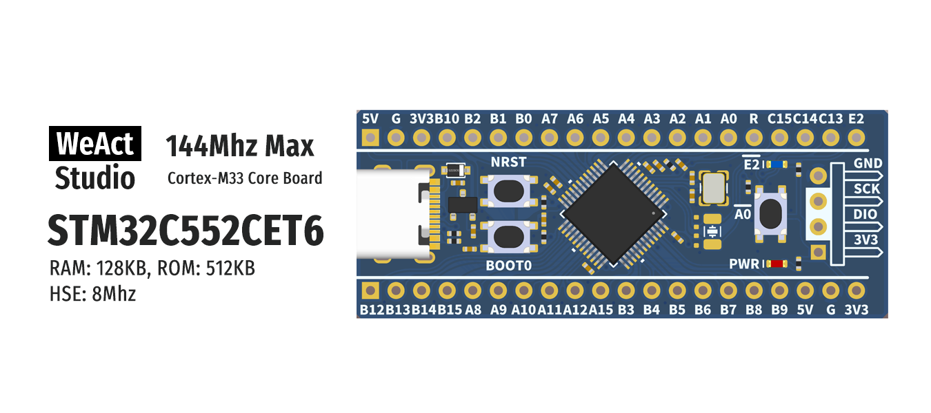
WeAct Studio STM32C552CET6 Cortex-M33 Core Board
WeAct Studio 144Mhz Max Cortex-M33 Core Board STM32C552CET6 RAM: 128KB, ROM: 512KB HSE: 8Mhz 5V G 3V3B10 B2 B1 B0 A7 A6 A5 A4 A3 A2 A1 A0 R C15C14C13 E2 NRST E2 GND SCK DIO 3V3 PWR BOOT0 A0 GND B12B13B14B15 A8 A9 A10A11A12A15 B3 B4 B5 B6 B7 B8 B9 5V
-
Thread
reading 24bit with I2S on nucleo stm32f411re
Hello, I am new to microcontroller programming. I am trying to read a digital microphone with a 24bit i2s interface. My problem is that the results I get are just uint16_t thus I loose some bits. I'm using st cube and HAL. The api documentation is: [c] /** * @brief Receive an amount of data in blocking mode * @param hi2s: pointer to a I2S_HandleTypeDef structure that contains * the configuration information for I2S module * @param pData: a 16-bit pointer to data buffer. * @param Size: number of data sample to be sent: * @note When a 16-bit data frame or a 16-bit
-
Thread
how can I read protect my STM32F4 with eclipse + openOCD JTAG ?
hello forum , I am using Eclipse + openOCD JTAG for downloading and debugging my aplication into STM32F4 after I finish my project I want read protect my code so that it is not stolen question : how can I read protect my STM32F4 with eclipse + openOCD JTAG thank you
Please have a look at this chapters in the reference manual of the stm32F4xxx microcontrollers (RM0090): 3.6.3 Read Protection (RDP) 3.6.1 Description of user option bytes 3.8.3 Flash option key register (FLASH_OPTKEYR) And after that you should read in the documentation
-
Article
Datei:Mini Shield V4 STM32F103 DS3231 AMS1117 2a.jpg
Mini Shield V4 für STM32F103+DS3231+AMS1117+LDR+DS1820
-
Article
Datei:Mini Shield V4 STM32F103 DS3231 AMS1117 3aa.jpg
komplettes Mini Shield V4 mit STM32F103+DS3231+AMS1117+(LDR+DS1820)
-
Article
Datei:Vcc-gnd.com-blue-pill-schematic-stm32f103c8t6.pdf
Schaltplan des blauen STM32F103C8T6 dev Boards von aliexpress, ebay und co. Nennt sich auch "Blue Pill".
-
Article
Datei:Mini Shield V4 STM32F103 DS3231 AMS1117 ohne R2 R5.jpg
Mini Shield V4 STM32F103 DS3231 AMS1117 ohne R2 da mit LDR, ohne R5 da kein TSOP
-
Thread
Current value Measured differs form the data sheet value in Low Power Sleep Mode for STM32L433Rc-p
Why the current measured form the microcontroller(Stm64 Nucleo L433RC- LPSleep mode) differ from the current value written in the datasheet? Hallo Everyone, I am using STM32L433RC -p microcontroller for current measurement. The current in the microcontroller was measured using STM32L496VGT6 module. I was doing current measurement for Low Power Mode(Low Power Sleep Mode). The current value given in the datasheet is in the raange of microampere, but the value which i read
-
Thread
GCC 4.3
\src\stm32f10x_spi.o obj\Debug\lib\src\stm32f10x_systick.o obj\Debug\lib\src\stm32f10x_tim.o obj\Debug\lib\src\stm32f10x_tim1.o obj\Debug\lib\src\stm32f10x_usart.o obj\Debug\lib\src\stm32f10x_vector.o obj
\src\stm32f10x_systick.o obj\Debug\lib\src\stm32f10x_tim.o obj\Debug\lib\src\stm32f10x_tim1.o obj\Debug\lib\src\stm32f10x_usart.o obj\Debug\lib\src\stm32f10x_vector.o obj\Debug\lib\src\stm32f10x_wwdg.o obj
-
Thread
arm-none-eabi-ld problem (resulting main.bin is 400MB)
MeasureMod.o I2CCom.o USARTCom.o stm32f10x_it.o stm32.a LIBOBJECTS = core_cm3.o stm32f10x_adc.o stm32f10x_dma.o stm32f10x_i2c.o stm32f10x_iwdg.o stm32f10x_pwr.o stm32f10x_tim.o stm32f10x_exti.o stm32f10x_gpio.o misc.o stm32f10x_rcc.o stm32f10x_usart.o stm32_eval.o system_stm32f10x.o LIBPATH = C:/gccfd/CodeSourcery/arm-none-eabi/lib/thumb CMDFILE = stm3210e_eval_flash.cmd STARTUP_FILE = startup_stm32f10x_ld-Mod > And here is the
-
Thread
Eclipse & OpenOCD: AHBAP; Sticky und Mem Read Error
Hi everyone, I'm using the STM32-P103 board with Eclipse and oocd 0.2.0. my problem is that I can't use debugging. I use this for OpenOCD: gdb_port 3333 # Work-area size (RAM size) = 20kB for STM32F103RB device set
You can look here: http://www.mikrocontroller.net/articles/STM32#Demo-Projekte There is a link to "ChaN's FAT-Module with STM32 SPI" In this project is a complete Eclipse configurationwhere is working fine.
-
Thread
Ds18b20 Problem
Thanks for the replies. So I tried using the scope again. I am indeed using it in between the STM32 and DS18b20. It seems last time the time scale was too short to see that. I can see that the STM32 is running fine. It sends the reset pulse and it reads the sensor as well. But it reads only "FF"s
If the problem still exists, the description in the file STM32_CunbeMX_DS18B20.pdf of the appendix may help.
-
Thread
ARM Cortex M7 64 bits floating point
ARM Cortex M7 64 bits floating point". There are only ARM Cortex M7 with ARM FPv4 (for example some STM32F7 Devices) and ARM Cortex M7 with ARM FPv5 (for example some STM32F7 or STM32H7 devices) extension. For Options of gcc look at gcc docs, of course: https://gcc.gnu.org/onlinedocs/gcc/ARM-Options.html
extension for double precision and is faster than the Atmel. http://www.st.com/en/microcontrollers/stm32h7-series.html?querycriteria=productId=SS1951 In the slower STM32F7 Series - which is slower - there are also some double precision devices. http://www.st.com/en/microcontrollers/stm32f7-series.html
-
Thread
Yagarto: Cortex-m3 linked ok, Cortex-m0 not
I have a lot of projects with stm32f1xx CPUs (cortex-m3), all is good with them. Now I decided to make project with stm32f051 (cortex-mo), and linker works with errors. I have several cpp files (task is to light-up LED), they are
done. I use Yagarto with GCC v.4.7.2. Here is output: arm-none-eabi-g++ -T"D:\Nute\_tmp_\f0test\STM32F051R8.ld" -Xlinker --gc-sections -Wl,-Map,f0test.map -mcpu=cortex-m0 -mthumb -o "f0test.elf" ./src/main.o ./lib/src/stm32f0xx_rcc.o ./lib/startup_stm32f0xx.o ./lib/system_stm32f0xx.o ./kl_lib/
-
Thread
General question: how does ARM core updates its registers?
trace down where all the registers (such as pll setting, IO, ...) get updated. For example, for the STM32F0 processor, below are the code to set system clock but the codes only have the registers that get modified, but how the register get updated by the processor? My guess is there is some type of interrupt
and compiler these specifically for the hardware. Here's a link to CMSIS: file:///C:/LinuxEmbSrc/STM32F0-Discovery_FW_V1.0.0/Libraries/CMSIS/Documentation/CMSIS_Core.htm