Hello everyone and thanks, I'm trying to describe the system through a
process, I'm pretty new to writing and can't get a proper description
due to the lack of use in wait.
If anyone has a good idea I can learn from I would love to hear
Attached files:
Daniel C. wrote:
> I'm trying to describe

Right on track!

Daniel C. wrote:
> can't get a proper description
> due to the lack of use in wait.

What description did you get? Show the code!
Daniel C. wrote:
> I'm pretty new to writing
No problem, all of us have been in earlier times.

> I'm trying to describe the system through a process
Show what you have so we have something to discuss.

> and can't get a proper description due to the lack of use in wait.
Show the problem. What happens and what do yout expect instead? In what
kind do you want to use the "wait"? Who in the toolchain is making
trouble?
:
Edited by Moderator
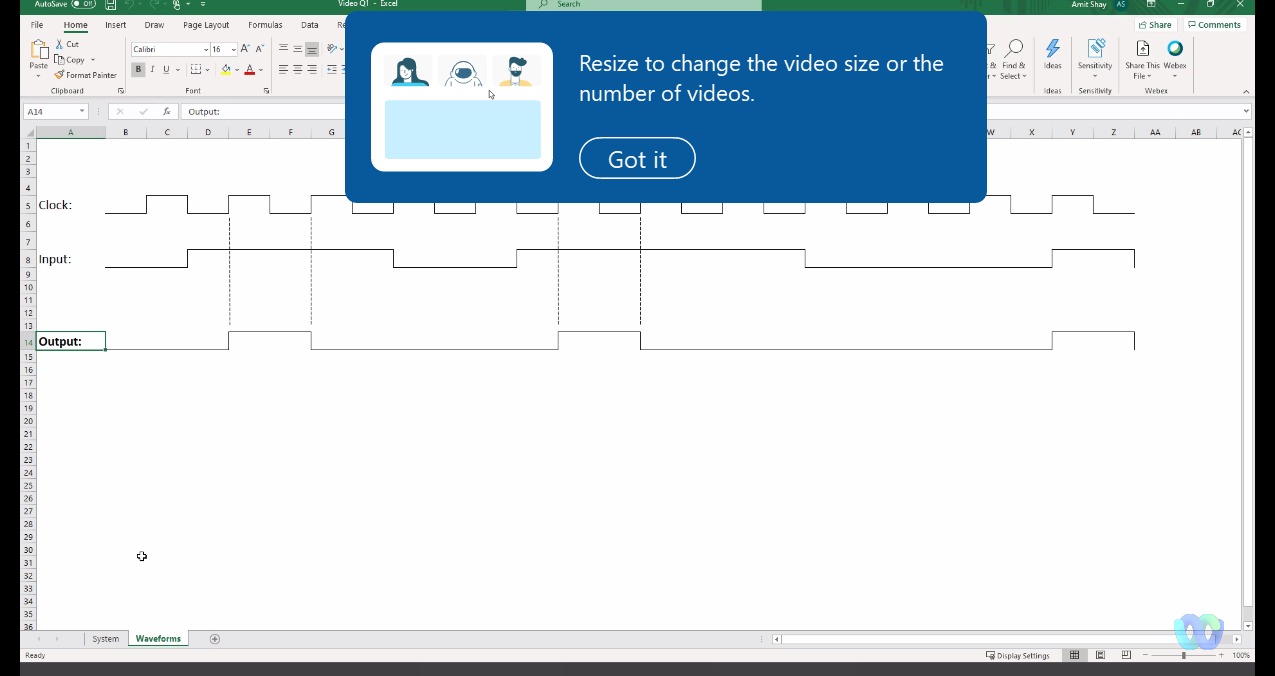
Daniel C. wrote:
> I'm pretty new

No problem since everyone did start earlier.


Daniel C. wrote:
I'm trying to describe the system through a process

What for a system, and what doesn't work?

Daniel C. wrote:
> If anyone has a good idea I can learn from I would love to hear

The best master's pro tip, which I have to give for now:
Never paint pictures and graphics in Excel! Never!
Use any CAD, make screenshots, LaTeX provices some nice tools for
different visiualization use cases, or if you have completly nothing
else, try paint.
But stop raping Excel in your pictures way.

If Excel is the only software at your computer and you have no admin
rights to install something better, make a line diagram.
Attached files:
In principle I was able to implement the system with my thinking and
planning, because the output signal is limited to one ascent so I put 2
skippers, I did a simulation in multi worked everything but can not
describe the system in vhdl using process
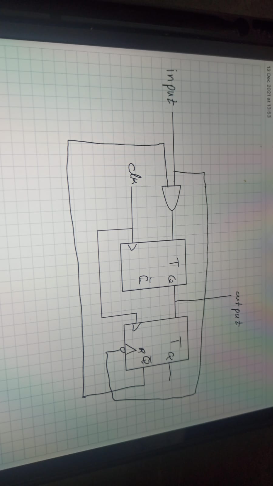
Daniel C. wrote:
> I did a simulation in multi worked everything
So lets see that code.

> but can not describe the system in vhdl using process
As already said: attach it here and show the error to get proper help.

All in all its fairly easy. Lets name those two flipflops ff1 and ff2:
1 | process begin |
2 | wait until rising_edge(clk); |
3 | ff1 <= inp AND NOT ff2; |
4 | ff2 <= ff1; |
5 | end process; |
6 | |
7 | outp <= ff1; |
Thats all, folks.

And best message of the day: you do not need no process at all:
1 | ff1 <= inp AND NOT ff2 when rising_edge(clk); |
2 | ff2 <= FF1 when rising_edge(clk); |
3 | outp <= ff1; |
Wühlhase wrote:
> make a line diagram.
Nice trick to use Excel that way. I'll keep in mind..  ;-)
:
Edited by Moderator
Thank you very much, I intend to understand how I create the conditions
in the processes (if, otherwise) as if in this case I could easily
describe it from knowledge of electrical engineering but I create a
system that is set to respond once within a single allowable, once I add
a sensitivity list in the process it does not give I have the option to
use standby
Note that there is a condition that the system responds once and for all
to the input signal, which is why I put a t.ff there with a rist in a
clock drop of the enabler
:
Edited by User
Daniel C. wrote:
> I intend to understand how I create the conditions in
> the processes (if, otherwise) as if in this case I could easily describe it >
from knowledge of electrical engineering but I create a system that is set > to
respond once within a single allowable
Add some punctuation marks where it helps to understand what you mean. I
didn't understand nothing at all...

> once I add a sensitivity list in the process it does not give I have the
> option to use standby
Thats a small unrelevant formalism. Use either one of them, all roads
lead to Rome.

A VHDL process is like a pencil, a VHDL concurrent description is like a
pen. Use can use either of them to write a description of your holiday
plans.


As already said: post your code together with the eror message and the a
screenshot of the waveform of the testbench.
:
Edited by Moderator
I will try again (=
Notice to the system, that the input signal is high The system only
needs to respond once, so I added a reset (in the figure) that is
scheduled to drop the clock of the input
Daniel C. wrote:
> Notice to the system, that the input signal is high The system only
> needs to respond once
Its really hard to worm it out of your given information, but as far as
I see: you want a simple edge detection.

Try that with Google translator:
http://www.lothar-miller.de/s9y/categories/18-Flankenerkennung

Daniel C. wrote:
> I will try again
I'll do also. A last time.

Where is your source code? Where is the error message? Or simply show
the original exercise of your homework!

Is it usual for you NOT answer the questions from those willing to help
you? Change that!
:
Edited by Moderator
process begin
if ( input='0') then
tff<='0';
else
wait until( rising_edge(clk));
tff<='1';
wait until( rising_edge(clk));
tff<='0';
wait until( falling_edge(input));
end if;

end process;
end Behavioral;
:
Edited by User
Maybe this code snippet will simulate somehow, but of course it is not
synthesizable.

Only a small fraction of simulable code is synthesizable to real
hardware. You have to use very specific syntax and you have to obey
strict coding rules. Check your code against the Synthesizers User
Maunal of the secret toolchain.
:
Edited by Moderator
I know it does not work (I tried to present the general idea because the
description presented here was not accurate)
I succeeded (=


entity Q_2 is
    Port ( input : in STD_LOGIC;
           clk : in STD_LOGIC;
           output : buffer STD_LOGIC:='0');
end Q_2;

architecture Behavioral of Q_2 is
 signal  en :  std_logic:='1';

begin
process (clk,input,en,output)
begin
if( output' event and output='0') then en<='0';
end if;
if(input' event and input='0') then en<='1';
end if;

if(en='0') then output<='0';
elsif(input='1' and clk' event and clk='1') then
output<=not(output);
end if;
end process;
end Behavioral;
Please log in before posting. Registration is free and takes only a minute.
Existing account
Do you have a Google/GoogleMail account? No registration required!
Log in with Google account
Log in with Google account
No account? Register here.