EmbDev.net

Forum: µC & Digital Electronics QSPI - STM32F7


von Petr K. (buzzer_klaun)


Attached files:

Rate this post
useful
not useful
Hello friends.

I have a small problem with my QSPI on STM32F7. I connect memory on this 
pins.

PB10 - CS flash
PF8 - IO0 (SI)
PF9 - IO1 (SO)
PF10 - SCK

And I call in main:
1
int main(void)
2
{
3
/* init NVICcm */
4
LL_Init();
5
/* init system clock */
6
SystemClock_Config();
7
8
qspi_init();
9
QSPI_Cmd(ENABLE);
10
QSPI_WriteEnable();
11
while (1){
12
blink_led();
13
LL_mDelay(200);}

And qspi_init() is OK, but the function QSPI_WriteEnable isn't work. It 
is wait on this line:
1
while(QSPI_GetFlagStatus(QSPI_FLAG_SM) == RESET){}

Any idea, what is wrong?
1
void qspi_init(void)
2
{
3
  LL_AHB1_GRP1_EnableClock(LL_AHB1_GRP1_PERIPH_GPIOF);
4
  LL_AHB1_GRP1_EnableClock(LL_AHB1_GRP1_PERIPH_GPIOB);
5
  LL_GPIO_SetPinMode(      GPIOF, LL_GPIO_PIN_8, LL_GPIO_MODE_ALTERNATE);
6
  LL_GPIO_SetAFPin_8_15(    GPIOF, LL_GPIO_PIN_8,  LL_GPIO_AF_10);
7
  LL_GPIO_SetPinMode(      GPIOF, LL_GPIO_PIN_9, LL_GPIO_MODE_ALTERNATE);
8
  LL_GPIO_SetAFPin_8_15(    GPIOF, LL_GPIO_PIN_9,  LL_GPIO_AF_10);
9
10
  /* SCK pin */
11
  LL_GPIO_SetPinMode(      GPIOF, LL_GPIO_PIN_10, LL_GPIO_MODE_ALTERNATE);
12
  LL_GPIO_SetPinPull(      GPIOF, LL_GPIO_PIN_10, LL_GPIO_PULL_NO);
13
  LL_GPIO_SetAFPin_8_15(    GPIOF, LL_GPIO_PIN_10, LL_GPIO_AF_9);
14
15
  /* CS pin */
16
  LL_GPIO_SetPinMode(      GPIOB, LL_GPIO_PIN_10, LL_GPIO_MODE_ALTERNATE);
17
  //LL_GPIO_SetPinOutputType(  GPIOB, LL_GPIO_PIN_10, LL_GPIO_OUTPUT_PUSHPULL);
18
  //LL_GPIO_SetPinPull(      GPIOB, LL_GPIO_PIN_10, LL_GPIO_PULL_UP);
19
  //LL_GPIO_SetPinSpeed(    GPIOB, LL_GPIO_PIN_10, LL_GPIO_SPEED_FREQ_VERY_HIGH);
20
  LL_GPIO_SetAFPin_8_15(    GPIOB, LL_GPIO_PIN_10,  LL_GPIO_AF_9);
21
22
  LL_AHB3_GRP1_EnableClock(LL_AHB3_GRP1_PERIPH_QSPI);
23
  /* Initialize QSPI ------------------------------------------------------ */
24
  QSPI_StructInit(&QSPI_InitStructure);
25
  QSPI_InitStructure.QSPI_SShift    = QSPI_SShift_HalfCycleShift;
26
  QSPI_InitStructure.QSPI_Prescaler = 4;  //Number = (216MHz / Fpoz)-1     (nyni Fpoz = 50MHz)
27
  QSPI_InitStructure.QSPI_CKMode    = QSPI_CKMode_Mode0;
28
  QSPI_InitStructure.QSPI_CSHTime   = QSPI_CSHTime_1Cycle;
29
  QSPI_InitStructure.QSPI_FSize     = 23;  //Number = 16MB is = (2^24) where 24-1 is Number
30
  QSPI_InitStructure.QSPI_FSelect   = QSPI_FSelect_1;
31
  QSPI_InitStructure.QSPI_DFlash    = QSPI_DFlash_Disable;
32
  QSPI_Init(&QSPI_InitStructure);
33
  QSPI_SetFIFOThreshold(0);
34
35
  /* Command default config */
36
  QSPI_ComConfig_StructInit(&QSPI_ComConfig_InitStructure);
37
  QSPI_ComConfig_InitStructure.QSPI_ComConfig_FMode       = QSPI_ComConfig_FMode_Indirect_Write;
38
  QSPI_ComConfig_InitStructure.QSPI_ComConfig_SIOOMode    = QSPI_ComConfig_SIOOMode_Disable;
39
  QSPI_ComConfig_InitStructure.QSPI_ComConfig_DummyCycles = 0;
40
  QSPI_ComConfig_InitStructure.QSPI_ComConfig_ABSize      = QSPI_ComConfig_ABSize_8bit;
41
  QSPI_ComConfig_InitStructure.QSPI_ComConfig_ADSize      = QSPI_ComConfig_ADSize_24bit;
42
  QSPI_ComConfig_InitStructure.QSPI_ComConfig_DMode       = QSPI_ComConfig_DMode_NoData;
43
  QSPI_ComConfig_InitStructure.QSPI_ComConfig_ADMode      = QSPI_ComConfig_ADMode_NoAddress;
44
  QSPI_ComConfig_InitStructure.QSPI_ComConfig_ABMode      = QSPI_ComConfig_ABMode_NoAlternateByte;
45
  QSPI_ComConfig_InitStructure.QSPI_ComConfig_IMode       = QSPI_ComConfig_IMode_1Line;
46
  QSPI_ComConfig_InitStructure.QSPI_ComConfig_DHHC        = QSPI_ComConfig_DHHC_Enable;
47
  QSPI_ComConfig_InitStructure.QSPI_ComConfig_DDRMode     = QSPI_ComConfig_DDRMode_Disable;
48
49
  QSPI_ITConfig(QSPI_IT_SM | QSPI_IT_TO, ENABLE);
50
51
  NVIC_SetPriority(QUADSPI_IRQn, NVIC_EncodePriority(NVIC_GetPriorityGrouping(), 0, 0));
52
  NVIC_EnableIRQ(QUADSPI_IRQn);
53
  QSPI_Cmd(ENABLE);
54
}
55
56
void QSPI_WriteEnable(void)
57
{
58
  /* Command Config for Write Enable */
59
    QSPI_ComConfig_InitStructure.QSPI_ComConfig_DHHC        = QSPI_ComConfig_DHHC_Disable;
60
    QSPI_ComConfig_InitStructure.QSPI_ComConfig_DDRMode     = QSPI_ComConfig_DDRMode_Disable;
61
    QSPI_ComConfig_InitStructure.QSPI_ComConfig_FMode       = QSPI_ComConfig_FMode_Indirect_Write;
62
    QSPI_ComConfig_InitStructure.QSPI_ComConfig_SIOOMode    = QSPI_ComConfig_SIOOMode_Disable;
63
    QSPI_ComConfig_InitStructure.QSPI_ComConfig_ABSize      = QSPI_ComConfig_ABSize_8bit;
64
    QSPI_ComConfig_InitStructure.QSPI_ComConfig_ADSize      = QSPI_ComConfig_ADSize_24bit;
65
    QSPI_ComConfig_InitStructure.QSPI_ComConfig_DMode       = QSPI_ComConfig_DMode_NoData;
66
    QSPI_ComConfig_InitStructure.QSPI_ComConfig_ADMode      = QSPI_ComConfig_ADMode_NoAddress;
67
    QSPI_ComConfig_InitStructure.QSPI_ComConfig_ABMode      = QSPI_ComConfig_ABMode_NoAlternateByte;
68
    QSPI_ComConfig_InitStructure.QSPI_ComConfig_IMode       = QSPI_ComConfig_IMode_1Line;
69
    QSPI_ComConfig_InitStructure.QSPI_ComConfig_Ins         = WRITE_ENABLE_CMD ;
70
    QSPI_ComConfig_InitStructure.QSPI_ComConfig_DummyCycles = 0;
71
    QSPI_ComConfig_Init(&QSPI_ComConfig_InitStructure);
72
73
    /* Switch to Autopolling mode for the end of the Command */
74
    while(QSPI_GetFlagStatus(QSPI_FLAG_BUSY) != RESET)
75
    {}
76
    QSPI_SetDataLength(0x01);
77
    QSPI_AutoPollingMode_SetInterval(0x10);
78
    QSPI_AutoPollingMode_Config(0x02, 0x02, QSPI_PMM_AND);
79
    QSPI_AutoPollingModeStopCmd(ENABLE);
80
    QSPI_SetDataLength(0x00);
81
82
    QSPI_ComConfig_InitStructure.QSPI_ComConfig_FMode  = QSPI_ComConfig_FMode_Auto_Polling;
83
    QSPI_ComConfig_InitStructure.QSPI_ComConfig_ADMode = QSPI_ComConfig_ADMode_NoAddress;
84
    QSPI_ComConfig_InitStructure.QSPI_ComConfig_DMode  = QSPI_ComConfig_DMode_1Line;
85
    QSPI_ComConfig_InitStructure.QSPI_ComConfig_Ins    = READ_STATUS_REG_CMD ;
86
    QSPI_ComConfig_Init(&QSPI_ComConfig_InitStructure);
87
88
    while(QSPI_GetFlagStatus(QSPI_FLAG_SM) == RESET)
89
    {}
90
    QSPI_ClearFlag(QSPI_FLAG_SM);
91
    QSPI_ClearFlag(QSPI_FLAG_TC);
92
    while(QSPI_GetFlagStatus(QSPI_FLAG_BUSY) != RESET)
93
    {}
94
    asm("NOP");
95
}

: Moved by Moderator
von Bülent C. (mirki)


Rate this post
useful
not useful
If you really want to have support, then you should give more info. 
Which flash you're using. Do you use the right commands according to the 
datasheet? From your pin configuration I can see that you're using the 
flash in a dual Modus, means two lines. You have to take in account that 
all the examples are designed for quad. Therefore copy paste wouldn't 
help you here.

von A. B. (Guest)


Rate this post
useful
not useful
Petr K. schrieb:
> void QSPI_WriteEnable(void)

>     QSPI_ComConfig_InitStructure.QSPI_ComConfig_FMode  =
> QSPI_ComConfig_FMode_Auto_Polling;
>     QSPI_ComConfig_InitStructure.QSPI_ComConfig_ADMode =
> QSPI_ComConfig_ADMode_NoAddress;
>     QSPI_ComConfig_InitStructure.QSPI_ComConfig_DMode  =
> QSPI_ComConfig_DMode_1Line;
>     QSPI_ComConfig_InitStructure.QSPI_ComConfig_Ins    =
> READ_STATUS_REG_CMD ;
>     QSPI_ComConfig_Init(&QSPI_ComConfig_InitStructure);
>
>     while(QSPI_GetFlagStatus(QSPI_FLAG_SM) == RESET)
>     {}
>     QSPI_ClearFlag(QSPI_FLAG_SM);
>     QSPI_ClearFlag(QSPI_FLAG_TC);
>     while(QSPI_GetFlagStatus(QSPI_FLAG_BUSY) != RESET)
>     {}
>     asm("NOP");

Although I've never used the autopolling feature: Why did you ever think 
of using this mode for write enable??? The "Write Enable" command just 
sets the "Write Enable" bit in the status register of the flash chip. So 
this works instantly, i. e. as soon as the command has been sent to 
the flash the very next "Status Read" command MUST return the status 
register with WE bit set or something is quite wrong. It doesn't make 
any sense to poll the status register several times for the WE bit to 
become set.

Automatic polling only makes sense for commands which require some time 
to finish like page programming, sector erase, mass erase.

von Petr K. (buzzer_klaun)


Attached files:

Rate this post
useful
not useful
Ou, sorry.

I use: single-SPI mode. It is describe in pdf file:
[[http://www.st.com/content/ccc/resource/technical/document/application_note/group0/b0/7e/46/a8/5e/c1/48/01/DM00227538/files/DM00227538.pdf/jcr:content/translations/en.DM00227538.pdf]]

And problem is:
I try send command to enable write. After send data, I wait on this 
line:
1
while(QSPI_GetFlagStatus(QSPI_FLAG_SM) == RESET){};

I compared registers, but I don't see any problem.

So I know:
1. GPIO is set correct
2. Init qspi is set wrong.

CLK -(yellow)
SI - (pink)
SO - (blue)

: Edited by User
von Joe F. (easylife)


Rate this post
useful
not useful
Petr K. schrieb:
> I use: single-SPI mode

- Are you also using a "normal" (non-QSPI) SPI flash memory?
- Which one?
- How do you handle HOLD and WR inputs?

von Petr K. (buzzer_klaun)


Rate this post
useful
not useful
Type of memory is: IS25LP128

Datasheet: [[http://www.issi.com/WW/pdf/25LP128.pdf]]

Connect to my MCU is:
PB10 - CS flash
PF8 - IO0 (SI)
PF9 - IO1 (SO)
PF10 - SCK

von Bülent C. (mirki)


Rate this post
useful
not useful
A. B. schrieb:
> Although I've never used the autopolling feature: Why did you ever think
> of using this mode for write enable??? The "Write Enable" command just
> sets the "Write Enable" bit in the status register of the flash chip. So
> this works instantly, i. e. as soon as the command has been sent to
> the flash the very next "Status Read" command MUST return the status
> register with WE bit set or something is quite wrong. It doesn't make
> any sense to poll the status register several times for the WE bit to
> become set.

I've here other experiences. It makes sense to poll the Status everytime 
even it's for the WE command.
In most of the cases you have different Status Registers for some 
commands (e.g. WE) and for the Memory Access itself.

von Bülent C. (mirki)


Rate this post
useful
not useful
Petr K. schrieb:
> while(QSPI_GetFlagStatus(QSPI_FLAG_SM) == RESET){};

What is inside of QSPI_FLAG_SM?


The Datasheet is saying:
WEL bit: The Write Enable Latch (WEL) bit indicates the status of the 
internal write enable latch. When the
WEL is “0”, the write enable latch is disabled and all write operations, 
including write status register, write
configuration register, page program, sector erase, block and chip erase 
operations are inhibited. When the
WEL bit is “1”, write operations are allowed. The WEL bit is set by a 
Write Enable (WREN) instruction. Each
write register, program and erase instruction must be preceded by a WREN 
instruction. The WEL bit can be
reset by a Write Disable (WRDI) instruction. It will automatically be 
reset after the completion of any write
operation.


Below how I would solve it with HAL
1
void QSPI_WriteEnable(QSPI_HandleTypeDef *QSPIHandle)
2
{
3
  QSPI_CommandTypeDef     sCommand;
4
  QSPI_AutoPollingTypeDef sConfig;
5
6
  /* Enable write operations */
7
  sCommand.InstructionMode   = QSPI_INSTRUCTION_1_LINE;
8
  sCommand.Instruction       = WRITE_ENABLE_CMD;
9
  sCommand.AddressMode       = QSPI_ADDRESS_NONE;
10
  sCommand.AlternateByteMode = QSPI_ALTERNATE_BYTES_NONE;
11
  sCommand.DataMode          = QSPI_DATA_NONE;
12
  sCommand.DummyCycles       = 0;
13
  sCommand.DdrMode           = QSPI_DDR_MODE_DISABLE;
14
  sCommand.DdrHoldHalfCycle  = QSPI_DDR_HHC_ANALOG_DELAY;
15
  sCommand.SIOOMode          = QSPI_SIOO_INST_EVERY_CMD;
16
17
  if (HAL_QSPI_Command(&hqspi, &sCommand, HAL_QPSI_TIMEOUT_DEFAULT_VALUE) != HAL_OK)
18
  {
19
    Error_Handler();
20
  }
21
  
22
  /* Configure automatic polling mode to wait for write enabling */  
23
  sConfig.Match           = 0x02;
24
  sConfig.Mask            = 0x02;
25
  sConfig.MatchMode       = QSPI_MATCH_MODE_AND;
26
  sConfig.StatusBytesSize = 1;
27
  sConfig.Interval        = 0x10;
28
  sConfig.AutomaticStop   = QSPI_AUTOMATIC_STOP_ENABLE;
29
  sCommand.Instruction    = READ_STATUS_REG_CMD;
30
  sCommand.DataMode       = QSPI_DATA_1_LINE;
31
32
  if (HAL_QSPI_AutoPolling(&hqspi, &sCommand, &sConfig, HAL_QPSI_TIMEOUT_DEFAULT_VALUE) != HAL_OK)
33
  {
34
    Error_Handler();
35
  }
36
}

von Petr K. (buzzer_klaun)


Rate this post
useful
not useful
I will try to rewrite from HAL to my code. Because I don't use HAL. I 
use LL, but QSPI is not support. When I will find solution I will put it 
here.

von A. B. (Guest)


Rate this post
useful
not useful
Bülent C. schrieb:

> I've here other experiences. It makes sense to poll the Status everytime
> even it's for the WE command.

Maybe you should have read (and try to understand) my comment:
Yes, of course, it does make sense to check the status register ONCE.
But to attempt to check it several times is plain rubbish.
Either it is already set on the first read after the Write Enable 
command,
or the command failed (for whatever reason). And if it failed, it 
doesn't make sense to check it again. It won't come on magically later.

If the Write Enable command failed, the only reasonable recovery is to 
reset the interface (and maybe the flash chip) and start over.

But anyway, the code posted is rather complete nonsense. Why would one 
enable an interrupt and then poll for this very same event???
(BTW: The same question was posted under different name on ST's 
community)

> In most of the cases you have different Status Registers for some
> commands (e.g. WE) and for the Memory Access itself.

What's that supposed to mean?

von Bülent C. (mirki)


Rate this post
useful
not useful
A. B. schrieb:
> Yes, of course, it does make sense to check the status register ONCE.
> But to attempt to check it several times is plain rubbish.
> Either it is already set on the first read after the Write Enable
> command,
> or the command failed (for whatever reason). And if it failed, it
> doesn't make sense to check it again. It won't come on magically later.

OK, for at least one Point we're on the same page. It really doesn't 
make sense to check the WEL Bit within the infinity Loop like the TO is 
doing that.
The HAL Driver is given the posibility to incorporate a timeout check 
for the polling of the WEL Bit. This is how I implemented it in my 
application.
1
/* Configure automatic polling mode to wait for write enabling */  
2
  sConfig.Match           = 0x02;
3
  sConfig.Mask            = 0x02;
4
  sConfig.MatchMode       = QSPI_MATCH_MODE_AND;
5
  sConfig.StatusBytesSize = 1;
6
  sConfig.Interval        = 0x10;
7
  sConfig.AutomaticStop   = QSPI_AUTOMATIC_STOP_ENABLE;
8
  sCommand.Instruction    = READ_STATUS_REG_CMD;
9
  sCommand.DataMode       = QSPI_DATA_1_LINE;
10
11
  if (HAL_QSPI_AutoPolling(&hqspi, &sCommand, &sConfig, HAL_QPSI_TIMEOUT_DEFAULT_VALUE) != HAL_OK)
12
  {
13
    Error_Handler();
14
  }
The Timeout is set to 100ms. This is in my point of view enough. If the 
WLE Bit isn't set within 100ms, then I've other issues what I'm trying 
to handle it somewhere else.

A. B. schrieb:
> If the Write Enable command failed, the only reasonable recovery is to
> reset the interface (and maybe the flash chip) and start over.
see above

A. B. schrieb:
> But anyway, the code posted is rather complete nonsense. Why would one
> enable an interrupt and then poll for this very same event???
I think you mean the TO's Code?! Yes, agree. The Code from him is really 
nonsense

A. B. schrieb:
>> In most of the cases you have different Status Registers for some
>> commands (e.g. WE) and for the Memory Access itself.
>
> What's that supposed to mean?
You would check the WLE Bit just one time, right? But it's not as simple 
as that! How do you know when exactly you Need to check the WLE Bit? 
Assume you're using your Code for different STM32's with different clock 
Settings or something like that?
That's the reason why I do it like posted above (multiple checks with 
timeout) makes more sense than to check the WLE just once.
The same is for the write/Program sequence. You could write 1 Byte or a 
complete Page at once. After the program command is performed you Need 
to wait until the Bytes are completly written. From where do you know 
how long you have to wait?

: Edited by User
von Petr K. (buzzer_klaun)


Rate this post
useful
not useful
OK. I have problems with it. So I will starting again.

I split my code to more function with show registers.
Now I have this function:
1
qspi_gpio_ini();  /* Init GPIO pins */
2
qspi_dma_init();  /* Init DMA  */
3
qspi_init();    /* Init QSPI */
4
qspi_config();    /* Config QSPI */
5
QSPI_Cmd(ENABLE);  /* Enable QSPI */

When I resolve this function I will set Write Enable function and other. 
:)

Here is Config pins. It is OK. It is work.
1
void qspi_gpio_ini(void)
2
{
3
  LL_AHB1_GRP1_EnableClock(LL_AHB1_GRP1_PERIPH_GPIOF);
4
  LL_AHB1_GRP1_EnableClock(LL_AHB1_GRP1_PERIPH_GPIOB);
5
  LL_GPIO_SetPinMode(      GPIOF, LL_GPIO_PIN_8, LL_GPIO_MODE_ALTERNATE);
6
  LL_GPIO_SetAFPin_8_15(    GPIOF, LL_GPIO_PIN_8,  LL_GPIO_AF_10);
7
  LL_GPIO_SetPinMode(      GPIOF, LL_GPIO_PIN_9, LL_GPIO_MODE_ALTERNATE);
8
  LL_GPIO_SetAFPin_8_15(    GPIOF, LL_GPIO_PIN_9,  LL_GPIO_AF_10);
9
10
  /* SCK pin */
11
  LL_GPIO_SetPinMode(      GPIOF, LL_GPIO_PIN_10, LL_GPIO_MODE_ALTERNATE);
12
  LL_GPIO_SetPinPull(      GPIOF, LL_GPIO_PIN_10, LL_GPIO_PULL_NO);
13
  LL_GPIO_SetAFPin_8_15(    GPIOF, LL_GPIO_PIN_10, LL_GPIO_AF_9);
14
15
  /* CS pin */
16
  LL_GPIO_SetPinMode(      GPIOB, LL_GPIO_PIN_10, LL_GPIO_MODE_ALTERNATE);
17
  LL_GPIO_SetAFPin_8_15(    GPIOB, LL_GPIO_PIN_10,  LL_GPIO_AF_9);
18
}

Init DMA. Here I don't know if it is work fine.
1
/**
2
 * Set register:
3
 * S0FCR = 0x00000021
4
 * s1FCR = 0x00000021
5
 * S2CR  = 0x16000419
6
 * S2FCR = 0x16000419
7
 * S2NDTR = 0x00000004
8
 * S2PAR = 0xA0001020
9
 * S3FCR = 0x00000021
10
 * S4FCR = 0x00000021
11
 * S5FCR = 0x00000021
12
 * S6FCR = 0x00000021
13
 * S7FCR = 0x00000021
14
 */
15
void qspi_dma_init(void)
16
{
17
  /*set from. DM00224583.pdf, from page 247, table 28 */
18
  LL_AHB1_GRP1_EnableClock(    LL_AHB1_GRP1_PERIPH_DMA2                  );
19
  LL_DMA_SetChannelSelection(    DMA2, LL_DMA_STREAM_2, LL_DMA_CHANNEL_11          );
20
  LL_DMA_SetDataTransferDirection(DMA2, LL_DMA_STREAM_2, LL_DMA_DIRECTION_PERIPH_TO_MEMORY  );
21
  LL_DMA_SetStreamPriorityLevel(  DMA2, LL_DMA_STREAM_2, LL_DMA_PRIORITY_LOW          );
22
  LL_DMA_SetMode(          DMA2, LL_DMA_STREAM_2, LL_DMA_MODE_NORMAL          );
23
  LL_DMA_SetPeriphIncMode(    DMA2, LL_DMA_STREAM_2, LL_DMA_PERIPH_NOINCREMENT      );
24
  LL_DMA_SetMemoryIncMode(    DMA2, LL_DMA_STREAM_2, LL_DMA_MEMORY_INCREMENT        );
25
  LL_DMA_SetPeriphSize(      DMA2, LL_DMA_STREAM_2, LL_DMA_PDATAALIGN_BYTE        );
26
  LL_DMA_SetMemorySize(      DMA2, LL_DMA_STREAM_2, LL_DMA_MDATAALIGN_BYTE        );
27
  LL_DMA_DisableFifoMode(      DMA2, LL_DMA_STREAM_2                    );
28
  LL_DMA_SetMemoryAddress(    DMA2, LL_DMA_STREAM_2, (uint32_t)FlashAddr          );
29
  LL_DMA_SetDataLength(      DMA2, LL_DMA_STREAM_2, sizeof(FlashAddr)          );
30
  LL_DMA_SetPeriphAddress(    DMA2, LL_DMA_STREAM_2, (uint32_t)&QUADSPI->DR        );
31
  LL_DMA_EnableIT_HT(        DMA2, LL_DMA_STREAM_2                    );
32
  LL_DMA_EnableIT_TC(        DMA2, LL_DMA_STREAM_2                    );
33
  LL_DMA_EnableStream(      DMA2, LL_DMA_STREAM_2                    );
34
  QSPI_DMACmd(ENABLE);  //enable DMAEN bit to DMA
35
}

ANd now. INIT QSPI. :)
1
/**
2
 * Set register:
3
 *
4
 * CR->PRESCALER   =   0x04
5
 * CR->SSHIFT    =  0x01
6
 * DCR->FSIZE    =   0x17
7
 */
8
void qspi_init(void)
9
{
10
  /* Initialize QSPI ------------------------------------------------------ */
11
  LL_AHB3_GRP1_EnableClock(LL_AHB3_GRP1_PERIPH_QSPI);
12
  QSPI_StructInit(&QSPI_InitStructure);
13
  QSPI_InitStructure.QSPI_SShift    = QSPI_SShift_HalfCycleShift;  //By default, the QUADSPI samples data 1/2 of a CLK cycle after the data is driven by the Flash memory
14
  QSPI_InitStructure.QSPI_Prescaler = 4;              //Number = (216MHz / Freq)-1  (Freq = 50MHz)
15
  QSPI_InitStructure.QSPI_CKMode    = QSPI_CKMode_Mode0;      //By default, nCS is high, deselecting the external Flash memory
16
  QSPI_InitStructure.QSPI_CSHTime   = QSPI_CSHTime_1Cycle;    //Chip select high time
17
  QSPI_InitStructure.QSPI_FSize     = 23;              //Number = 16MB is = (2^24) where 24-1 is Number
18
  QSPI_InitStructure.QSPI_FSelect   = QSPI_FSelect_1;        //Flash memory selection
19
  QSPI_InitStructure.QSPI_DFlash    = QSPI_DFlash_Disable;    //
20
  QSPI_Init(&QSPI_InitStructure);
21
}

After init is configure...
1
/**
2
 * Set registers:
3
 * CCR->ADSIZE  =  0x02
4
 * CCR->DHHC  =  0x01
5
 * CCR->IMODE  =  0x01
6
 */
7
void qspi_config(void)
8
{
9
  QSPI_SetFIFOThreshold(0);
10
11
  /* Command default config */
12
  QSPI_ComConfig_StructInit(&QSPI_ComConfig_InitStructure);
13
  QSPI_ComConfig_InitStructure.QSPI_ComConfig_FMode       = QSPI_ComConfig_FMode_Indirect_Write;    //QUADSPI is in indirect write mode, where bytes are sent to the Flash memory during the data phase
14
  QSPI_ComConfig_InitStructure.QSPI_ComConfig_SIOOMode    = QSPI_ComConfig_SIOOMode_Disable;      //Send instruction only-once
15
  QSPI_ComConfig_InitStructure.QSPI_ComConfig_ABSize      = QSPI_ComConfig_ABSize_8bit;        //number of alternate bytes
16
  QSPI_ComConfig_InitStructure.QSPI_ComConfig_ADSize      = QSPI_ComConfig_ADSize_24bit;        //max. addressable memory (2^24)
17
  /* this set is from DM00224583.pdf, page 409, picture 63 */
18
  QSPI_ComConfig_InitStructure.QSPI_ComConfig_IMode       = QSPI_ComConfig_IMode_1Line;        //instruction phase is skipped
19
  QSPI_ComConfig_InitStructure.QSPI_ComConfig_ADMode      = QSPI_ComConfig_ADMode_NoAddress;      //address phase is skipped
20
  QSPI_ComConfig_InitStructure.QSPI_ComConfig_ABMode      = QSPI_ComConfig_ABMode_NoAlternateByte;  //alternate-bytes phase is skipped
21
  QSPI_ComConfig_InitStructure.QSPI_ComConfig_DummyCycles = 0;                    //Set dummy cycle
22
  QSPI_ComConfig_InitStructure.QSPI_ComConfig_DMode       = QSPI_ComConfig_DMode_NoData;        //data phase is skipped
23
24
  QSPI_ComConfig_InitStructure.QSPI_ComConfig_DHHC        = QSPI_ComConfig_DHHC_Enable;        //Delay the data output by 1/4 of a QUADSPI output clock cycle.
25
}

And the last function where I don't know.... Is it configure good?

von Petr K. (buzzer_klaun)


Attached files:

Rate this post
useful
not useful
I modificated speed, and now I get this datas.... Now it is better, 
but....

von Petr K. (buzzer_klaun)


Attached files:

Rate this post
useful
not useful
Hello,

I analyze my problem. And my init qspi is good, because:
1. Init GPIO is OK. Communication is workign.
2. Init qspi (default setting) is good, because I can send everything.

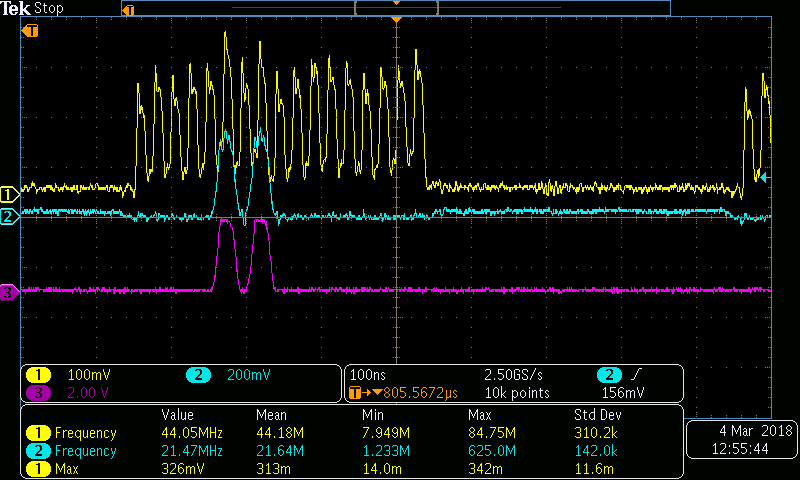
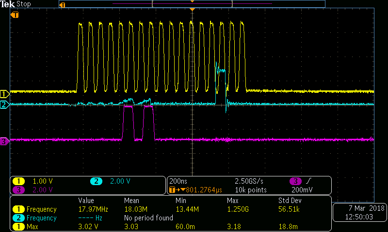
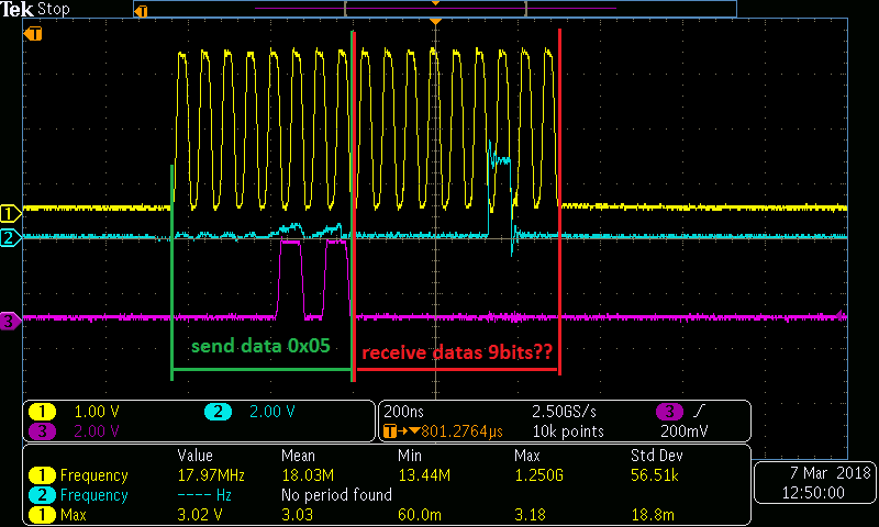
And now, I'm looking on my program:
1. Send command 0x06 is OK.
2. Send command 0x05 is OK.
3. Receive datas is wrong. Because they have 9 bits.

And I don't know, why the receive datas have 9bits.

What do you think, what is wrong?
1
/* Send 0x05 and receive 1 byte */
2
    while(QSPI_GetFlagStatus(QSPI_FLAG_BUSY) != RESET)
3
    {}
4
    QSPI_AutoPollingMode_SetInterval(0x10);//Number of CLK cycles between to read during automatic polling phases.
5
    QSPI_AutoPollingMode_Config(0x02, 0x02, QSPI_PMM_AND);  //set compare mode for autopolling
6
    QSPI_AutoPollingModeStopCmd(ENABLE);  //enable autopolling
7
    QSPI_SetDataLength(0x00);  //data lenght is 0
8
9
    QSPI_ComConfig_InitStructure.QSPI_ComConfig_FMode  = QSPI_ComConfig_FMode_Auto_Polling;
10
    QSPI_ComConfig_InitStructure.QSPI_ComConfig_ADMode = QSPI_ComConfig_ADMode_NoAddress;
11
    QSPI_ComConfig_InitStructure.QSPI_ComConfig_DMode  = QSPI_ComConfig_DMode_1Line;
12
    QSPI_ComConfig_InitStructure.QSPI_ComConfig_Ins    = READ_STATUS_REG_CMD;
13
    QSPI_ComConfig_Init(&QSPI_ComConfig_InitStructure);
14
15
    while(QSPI_GetFlagStatus(QSPI_FLAG_SM) == RESET)

von Petr K. (buzzer_klaun)


Rate this post
useful
not useful
Ok. Problem with more 1bit is here:

Bad:
1
QSPI_InitStructure.QSPI_SShift    = QSPI_SShift_HalfCycleShift

Good:
1
QSPI_InitStructure.QSPI_SShift    = QSPI_SShift_NoShift;

But program is still waiting on this line:
1
while(QSPI_GetFlagStatus(QSPI_FLAG_SM) == RESET){};

: Edited by User
Please log in before posting. Registration is free and takes only a minute.
Existing account
Do you have a Google/GoogleMail account? No registration required!
Log in with Google account
No account? Register here.