Hello,

I'm currently building my first stepper motor driver, a bipolar stepper,
4.5-48V 1A phase current with 4.5 Ohm phase resistance. I've built the
circuit of the L6206 following the "Typical application" in the data
sheet and controlling it with an AVR ATmega.

Basically it works fine, but the current is much too high. At 12V my
2.5A power supply switches off and the L6206 gets hot very quick. At 7V
the current at stand still is more than 1.5A, running it is at 1A.

So I suppose I have to limit the current, but I am not sure how. The
datasheet mentions an integrated PWM current control but I can't find
any further information on how to use it. It explains how to the
overcurrent protection can be used to roughly regulate the load current
what I have tried, it works but the motor then runs choppy and I feel
sorry for it.

Another thing I don't understand is why the driver still works if I
remove the charge pump?

Greetings,
Torsten
Torsten wrote:
> Hello,
>
> I'm currently building my first stepper motor driver, a bipolar stepper,
> 4.5-48V 1A phase current with 4.5 Ohm phase resistance. I've built the
> circuit of the L6206 following the "Typical application" in the data
> sheet and controlling it with an AVR ATmega.
>
> Basically it works fine, but the current is much too high. At 12V my
> 2.5A power supply switches off and the L6206 gets hot very quick. At 7V
> the current at stand still is more than 1.5A, running it is at 1A.
>
> So I suppose I have to limit the current, but I am not sure how. The
> datasheet mentions an integrated PWM current control but I can't find
> any further information on how to use it. It explains how to the
> overcurrent protection can be used to roughly regulate the load current
> what I have tried, it works but the motor then runs choppy and I feel
> sorry for it.
>
> Another thing I don't understand is why the driver still works if I
> remove the charge pump?
>
Take a look at pin 13 and 24, there you can adjust the max. current with
an external resistor.

If this doesn`t work as expected - show picts, schematic and the usual
stuff needed to debug something like this.

regards

MiWi
MiWi wrote:
> Take a look at pin 13 and 24, there you can adjust the max. current with
> an external resistor.

Thanks for the suggestion, I already did try that, it works to limit the
current but the motor runs awfully noisy and choppy and loses steps. I
suppose that's because in effect it is like very slow PWM. I doesn't
seem to be possible to improve that by reducing the shut down time of
the overcurrent protection below what you get with 100kOhm and 5.6nF so
I guess that is not an option.

I'll try to PWM the enable voltage as it seems to be possible with the
L6206.

I really wonder how one is supposed to regulate the current with the
L6206 since it doesn't have a reference voltage pin like most other
drivers have.

Maybe I bought the wrong driver, it doesn't seem to go well with the
stepper motor I have. I think I'll go for a DRV8825, it looks very
interesting and supports microstepping which the motor is actually
optimized for, it has a simple STEP/DIR interface and allows for current
regulation.

BTW I think we could have this conversation in German, but since I opted
to post on EmbDev.net (which doesn't seem to be the best choice) we're
stuck with English...
Torsten wrote:
> MiWi wrote:
>> Take a look at pin 13 and 24, there you can adjust the max. current with
>> an external resistor.
>
> Thanks for the suggestion, I already did try that, it works to limit the
> current but the motor runs awfully noisy and choppy and loses steps. I
> suppose that's because in effect it is like very slow PWM. I doesn't
> seem to be possible to improve that by reducing the shut down time of
> the overcurrent protection below what you get with 100kOhm and 5.6nF so
> I guess that is not an option.
>
> I'll try to PWM the enable voltage as it seems to be possible with the
> L6206.
>
> I really wonder how one is supposed to regulate the current with the
> L6206 since it doesn't have a reference voltage pin like most other
> drivers have.


take a look at fig 7 & 8 and you will see that there is a referece
voltage for overcurrent.

So it looks like that your pwm interacts somehow with the currentlimits
@ Pin7/24 so...


I can (and will) only repeat once more:

If this doesn`t work as expected - show picts, schematic and the usual
stuff needed to debug something like this.


regards

MiWi
Torsten wrote:
> I'll try to PWM the enable voltage as it seems to be possible with the
> L6206.

Just to follow up... this works only somewhat, the current can be
limited and the motor runs better as with the overcurrent protection,
but it still runs rough and seems to lose steps (tried with 1, 4 and
30kHz PWM frequency).
Attached files:
-

IMG_20160215_032610.jpg
200 KB
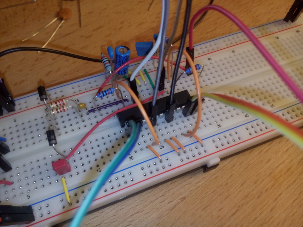
MiWi wrote:
> take a look at fig 7 & 8 and you will see that there is a referece
> voltage for overcurrent.

Yes, I am aware of that, and I chose the resistors to get a threshold of
1A. The current is limited as expected, but I guess the choppiness is
caused by t_DISABLE and t_DELAY.
So I have set C_EN and R_EN to 1nF and 10K to reduce both timings and
the motor does run a lot smoother but still not very nice.
It runs perfectly fine without overcurrent protection.

Overcurrent detection is meant to detect a fault condition, not to
control normal operations, or am I wrong? It feels like using exceptions
to control normal program flow.
The L6206 simply does not offer current control, while the L6207 does.
But it is way too expensive I think.

> So it looks like that your pwm interacts somehow with the currentlimits
> @ Pin7/24 so...

I did not do any PWM while testing overcurrent protection.

> I can (and will) only repeat once more:
>
> If this doesn`t work as expected - show picts, schematic and the usual
> stuff needed to debug something like this.

I've built the circuit on a breadboard exactly following the diagram
"Figure 12. Typical Application". A picture of the circuit is attached.
Please log in before posting. Registration is free and takes only a minute.
Existing account
Do you have a Google/GoogleMail account? No registration required!
Log in with Google account
Log in with Google account
No account? Register here.