VHDL coding Question

Moderator (Company: Titel) #3896622
Rate this post
useful
not useful
> Untitled.png
My VHDL files end with .vhdl, not with .png...
If you would have posted the code as some ASCII characters, it would be 
a work of 5 minutes to answer all of your simple questions.

Michael wrote:
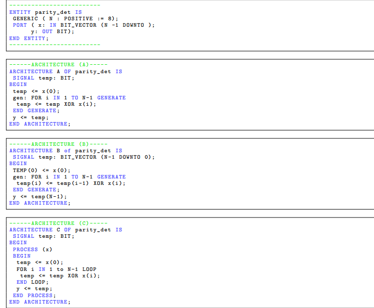
> I was wondering which would work better before I try it out.
And what are your desults after wondering a little bit?

> Any advice on which and why?
No one of them will not pass the syntax check due to the error in the 
port list. In B too much temps are used, but the optimizer will kick 
them out. And C will get correct behaviour on real hardware, but it will 
generate a wrong simulation result due to a incomplete sensitivity list.

> Also is there a difference between using signal and variable in this
> case?
In A and B no variable can be used. In C one signal is missing in the 
sensitivity list, and so the simulation result would be different, if 
temp was a variable.

Result: after adding a 0 in the port list all of them will generate 
almost the same hardware, but C will fail in the simulation.
(Company: student) #3900797
Rate this post
useful
not useful
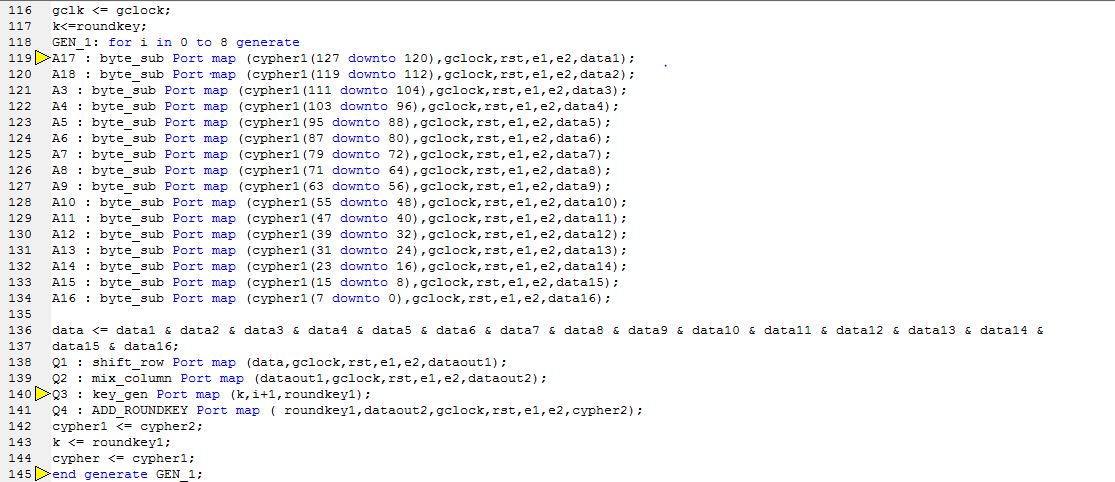
I have to replicate this logic 9 times and I applied generate statement 
in component instantiation, it is not showing any error in syntax but 
not giving any output showing uuuuuuuuuuuuuu. I am attaching that code . 
please help me out urgently.
 where:  roundtkey,roundkey1,cypher,cypher1(0th round output) ,cypher2 
are 128 bits.
         and i is for round. we need round only in key generation. we 
have to replicate same steps for 9 rounds and each round's output will 
go to other round's byte substitution step.
Attached files:
Moderator (Company: Titel) #3901074
Rate this post
useful
not useful
Niharika Agrawal wrote:
> Now I am attaching .v file.
In common use a .v file is a Verilog  file. And within a .vhd file I 
would expect VHDL code (as the forum software does also)...

> I am attaching that code .
As far as I see the problem is not in the posted code. It must be 
somewhere else. You posted only some port wiring, this has nothing to do 
with an U (=uninitialized) result...

BTW: what's the testbench for your code?
Moderator (Company: Titel) #3901242
Rate this post
useful
not useful
Niharika Agrawal wrote:
> I am attaching the main code here.
Nice try...
full.vhdl.txt (39.2 KB, 0 downloads)
code1.vhdl.txt (5.13 KB, 0 downloads)
But .txt is NOT the same as .vhdl
You know what a filename extension is? And what it is used for?

> I am attaching the main code here.
The code is ugly formatted: absolutely no structure is visible. 
Identation seems to be unknown...
But I think even after adding some identation it is not possible to 
recognize a structure in that VHDL description. Do you have a sketch or 
a structure drwaing of the whole thing?
Remeber: VHDL is a hardware DESCRIPTION language. And to DESCRIBE 
something you must have a picture of it (at least a picture inside your 
head). Without such a picture you never can DESCRIBE something so that a 
third party (here it is the synthesizer) understands what you want to 
get.

Let me be honest: hopefully you will not try to implement this thing on 
real hardware.

This is not a way to generate clocks for FPGAs:
1
  process (clk,a1) begin
2
    if(clk'event and clk = '0') then
3
      b1 <= a1;
4
    else
5
      b1 <= b1;
6
    end if;
7
  end process;
8
  gclock <= clk and b1;
9
  gclk <= gclock;
And also a1 in the sensitivity list is redundant.

In opposite most of the other modules will simulate wrong due to an 
incomplete sensitivity list:
1
process (clk) is begin      -- rst is missing --> simulation is wrong
2
  if rst = '1' then
3
    DATAOUT <= (others => '0');
4
  elsif (clk='1' and clk'event) then

You have some multiple sources in the code (I kept your "formatting" 
here):
1
-- round 0                  -- do you think the synthesizer evaluates comments?
2
begin
3
a1 <= e1 or e2;
4
process (clk,a1)
5
begin
6
if(clk'event and clk = '0') then
7
b1 <= a1;                    -- assignment to b1
8
else
9
b1 <= b1;
10
end if;
11
end process;
12
gclock <= clk and b1;
13
gclk <= gclock;
14

15
m1 : ADD_ROUNDKEY Port map ( state,roundkey,gclock,rst,e1,e2,cypher1);
16

17
-- round 1 to 9             -- do you think the synthesizer evaluates comments?
18
a1 <= e1 or e2;
19
process (clk,a1)
20
begin
21
if(clk'event and clk = '0') then
22
b1 <= a1;                      -- additional assignment to b1
23
else
24
b1 <= b1;
25
end if;
26
end process;
27
gclock <= clk and b1;
28
gclk <= gclock;
That will funnily enough work in simulation because both of the 
assignments lead to the very sam result, but it will NEVER EVER work 
with through synthesizer in real hardware.

And with what testbench (remember my question?) do you get these 
"UUUUUUU" result on what output? Can you show a screenshot of that 
"UUUUUUUU". What else do you expect there? Did you check each of those 
big bunch of submodules and functions for functionality independent from 
the others?
(Company: student) #3902072
Rate this post
useful
not useful
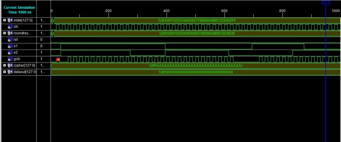
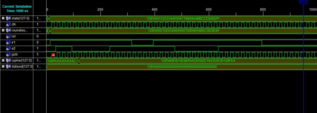
Hey
comments are only for my understanding and I already corrected that 
process thing but sorry I sent you the unmodified code and the clock 
which I am generating is gated clock using latch and I think all these 
things are correct because I am getting the right output for round = 1 
means if I am writing "key_gen Port map (k,1,roundkey1)" without using 
any loop.

Attaching here test bench waveform for both in loop or without loop.
Thank you.
Attached files:
Guest #3902267
Rate this post
useful
not useful
Niharika Agrawal wrote:
> Hey
> comments are only for my understanding and I already corrected that
> process thing but sorry I sent you the unmodified code and the clock
> which I am generating is gated clock using latch and I think all these
> things are correct because I am getting the right output for round = 1
> means if I am writing "key_gen Port map (k,1,roundkey1)" without using
> any loop.
>
> Attaching here test bench waveform for both in loop or without loop.
> Thank you.

well, then it looks like everything seems to work! Why are you asking?
Guest #3902738
Rate this post
useful
not useful
three options:
1) belive what Lothar Miller is telling you, do it, be happy once
2) learn on how to correctly configure FPGA, see that Lothar is right, 
be happy some more times
3) stay with your belief, that you are actually right, and keep trying

Clock gating IS very seldom the right thing to do - especially for 
newbies (your professor should have told you already). It tends to 
induce small errors that looove to sum up with every cycle until bits 
are lost/drivers conflicting/... This is what your simulation is telling 
you.
Guest #4014781
Rate this post
useful
not useful
Hello everybody

I have to do a projekt:

The projekt:
In this projekt a simple WAV player will be implemented using an FPGA. 
The WAV player is able to play music which is digitally stored in a 
semiconductor memory device. The basic principle of the WAV player is 
the same as the principle of an MP3 player. However, no compression 
scheme is used to store the digital audio data. Thus, in contrast to an 
MP3 player music is  stored in an uncompressed format in the WAV 
player's memory device.

Can someone write me the vhdl code please  ?

Reply

Please log in before posting.

or

Log in with Google account

Registration is free and takes only a minute.

Register now