Hi, I am trying to simulate a ring oscillator in Modelsim using the
delay (.sdo) file generated by Quartus to get the relationship between
frequency and # of gates. For some reason whenever I simulate this I get
the exact same frequency, 1.6 GHz, regardless if my oscillator has 1
gate or 1000. My simulation is basically just:

assign B = ~A;
assign C = ~B;
assign A = ~C;

and then expanded in a generate loop for more gates.

An I doing something wrong with the sdo file? I first compile in
Modelsim, then select Simulate, add the sdo file, then start.

Thanks
Guest
#3389366
Are you sure that you don't generate 1000
3-Inverter Loops that just sit next to each
other?

Gerhard
I don't know exactly what happens at the other end of the compiler, but
I assumed that since every intermediate signal depends on the initial
one that it wouldn't separate the inverters.
Guest
#3389443
You cannot simulate analog behavior this way. You only can simulate
something similar.
Guest
#3389604
you can simulate this by adding an delay assignment.
I thought that the delay the simulator used (generated by Quartus) would
be the same as if I manually added a delay assignment, only I don't know
what delay to use in real time. So nothing should be analog in the
simulation. All I really want to know is the delay across a single gate,
which should accumulate for larger loops, but I'm not confident in my
simulation due to the weird results.
Guest
#3389695
Again, you cannot (in no case) simulate the behavior of a ring
oscillator, because this function uses analog behavior. The Simulator
can only simulate digital behavior.
Of course all circuit behavior is analog behavior, calling it digital is
an approximation. Given enough gates the output of the oscillator should
be approximately digital. If I just attach a constant delay to each
assignment then the oscillator works perfectly in simulation, only I
have to guess what the gate delay is. I was hoping the synthesized delay
file would have a more accurate delay.
Chris C1111 wrote:
> Hi, I am trying to simulate a ring oscillator in Modelsim using the
> delay (.sdo) file generated by Quartus to get the relationship between
> frequency and # of gates. For some reason whenever I simulate this I get
> the exact same frequency, 1.6 GHz, regardless if my oscillator has 1
> gate or 1000.
Beside the fact that the frequency will be much differtent in real life:
whats the initial value for all the gates? How do you assign it?
I use an external clock and a counter with an initialization signal.

assign A = (INIT) ? 1'b1 : ~C;

This should initialize all signals.
Chris C1111 wrote:
> assign A = (INIT) ? 1'b1 : ~C;
And the other ones?
If I set one signal, all the others should be initialized automatically.
For the example in my first post if I set A = 1, then B and C are
automatically initialized to 0 and 1 since during initialization there
is no combinational loop.
Chris C1111 wrote:
> For the example in my first post if I set A = 1, then B and C are
> automatically initialized to 0 and 1 since during initialization there
> is no combinational loop.
And after that all "even" signals will be 1 and all "odd" signals will
be 0. And thenn, what will happen if they circle araound? Will there
(for any single signal) be a difference between the short "10101"
sequence and the long "10101010101010101010101010101010101010101"
cycling around? No, in both cases each single signal will toggle at
maximum speed...

So try it with passing through the signal and only toggle its polarity
on one bit:
assign B = ~A;
assign C = B;
assign A = C;
But then you will have to tell the synthesizer that it has to "keep" all
of the signals. In VHDL for Xilinx you could do it this way:
http://www.lothar-miller.de/s9y/categories/29-Ringoszillator
(try the google translator, its German)
Guest
#3390361
assign B = #delay ~A;

where is the delay per inverter  in your model?
When I synthesize it in Quartus it generates a delay file (.sdo) which I
use while I run my simulation.
I think I have it figured out. In order to keep the compiler from over
simplifying the intermediate gates into a single LUT I need to set all
the intermediate signals as outputs. Thanks for the replies!
Guest
#3390881
You don't need to specify the intermediate signals as output.
As Lothar told you already, you have to tell Quartus to don't optimize
these signals.

Take a look at the attributes keep, noprune and preserve.

Can't remember right now which one did the trick.

I adopted Lothars code to run on a de0nano using Quartus II 12.0.
dasdgw wrote:
> I adopted Lothars code to run on a de0nano using Quartus II 12.0.
In VHDL? What are the results? Can you show the code? I find it very
interesting to compare different architectures...   ;-)
Thanks for pointing that out! Somehow I completely missed Lothar's last
post. What you said makes perfect sense, I can't believe I missed that.
Why does wikipedia state the output frequency is 1/(2*N×inverter delay)?

http://en.wikipedia.org/wiki/Ring_oscillator
(the figure caption)

Edit: I don't think what you said is correct. Immediately after
initialization, everything is stable except for the first inverter, so
the last inverter won't toggle until every inverter before it has. At
that point every inverter is stable again except for the first one.
Chris C1111 wrote:
> Edit: I don't think what you said is correct.
Hmmm...

You and wikipedia are right. I did a short test with symbolic delay:
1 | |
2 | |
3 | |
4 | |
5 | |
6 | |
7 | |
8 | |
9 | |
10 | |
11 | |
12 | |
13 | |
14 | |
15 | |
16 | |
17 | |
18 | |
19 | |
20 | |
21 | |
22 | |
23 | |
24 | |
25 | |
26 | |
27 | |
28 | |
29 | |
30 | |
31 | |
32 | |
33 | |
I will check this on hardware later... ;-)
Attached files:
-
 Ringo_3Bit.png
(5.8 KB)
Ringo_3Bit.png
(5.8 KB)
-
 Ringo_21Bit.png
(5.8 KB)
Ringo_21Bit.png
(5.8 KB)


Without the attribute "keep" all of the stages are optimized down to 1
single mux-stage (see screenshots). Of course you could invent an output
pin for each bit (as you did), but FPGA IO pins in real life are to
expensive for such a simple task...
Attached files:
-
 Ringo_21bit_keep.png
(4 KB)
Ringo_21bit_keep.png
(4 KB)
-
 Ringo_21bit_no_keep.png
(5.7 KB)
Ringo_21bit_no_keep.png
(5.7 KB)
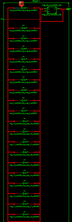
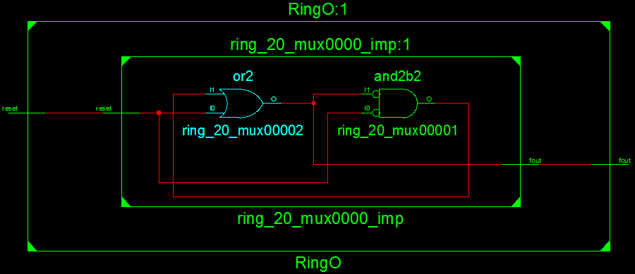
Yes I didn't know about the keep attribute. Using this my oscillator
works well in simulation and on my de0 (although as you predicted the
frequency differs greatly). I get about 250MHz with 21 gates on
hardware, I'm too scared to go much faster than that.
Chris C. wrote:
> I get about 250MHz with 21 gates on
> hardware, I'm too scared to go much faster than that.

I used ring oscillators with up to 1.2GHz with a chain length which
makes sure, that all inverters fully saturate before the signal is
looped back to them. According to the switching time and routing, it is
possible to tune the model's delays appropriately.

http://www.96khz.org/htm/noisegenerator2.htm
Reply
Only registered users may reply in this topic.