Good evening.

I encountered some problems during my Project with the ESP 8266 in
combination with the IRF510N on a circuit board.
I wanted to build an RGB controller for common anode RGB LED strips. The
project and the code are done, and I tested the whole project on my
breadboard, which worked as expected. So I soldered everything together
on a piece of perf board.

That's where my problems start to occur. If I wanted to switch out the
light, I set my dedicated pin to LOW. This works fine on the breadboard,
but not on my soldered circuit board. On my soldered circuit, the LEDs
are not entirely turned off, but instead, flicker on very low brightness
randomly.

This does not happen on the Breadboard. I checked everything for shorts
or cold solder joints. Everything is in order. I probed with my
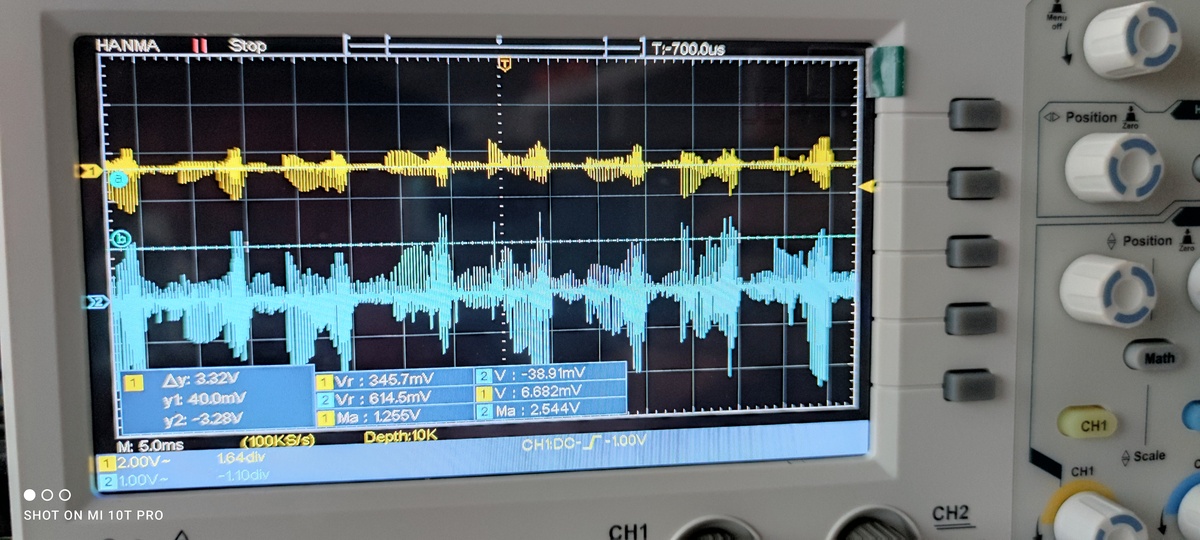
oscilloscope and discovered, that the used IRF510N Mosfets have very
high background noise. On the breadboard, the noise is around 1.2v max
and 800mV and on the perf board its around 2V and 2.5V max. According to
the datasheet of the IRF510N, it will trigger at a threshold of around 2
v, which I guess, causes the flickering.

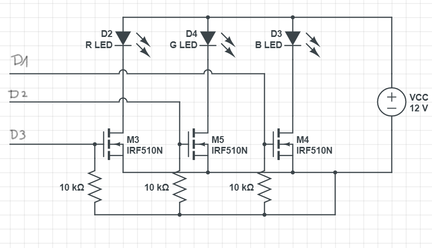
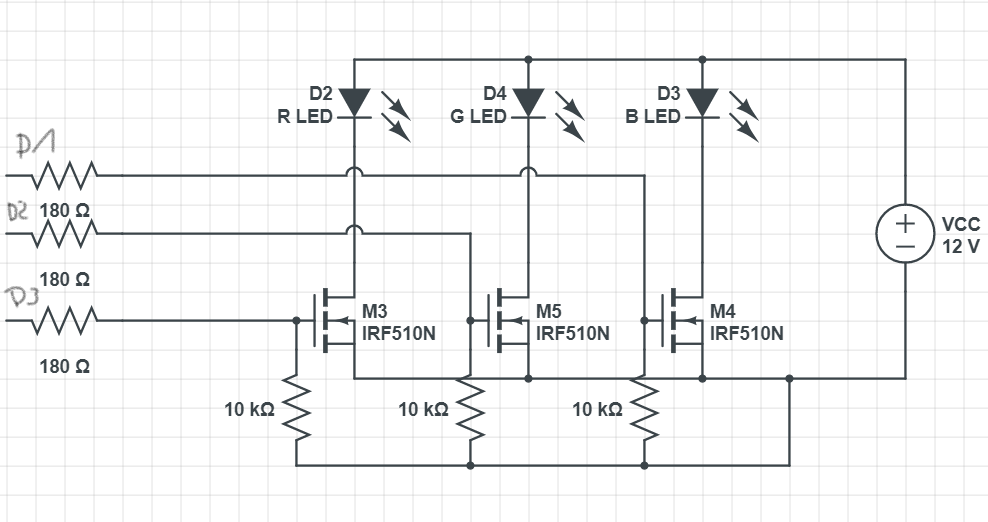
My problem now is, I don't know why it is, and how to avoid that. I
already experimented with resistors between the ESP pin and the Gate of
the MOSFET, with a resistor between the gate and GND and with both
together. Everything I tried so far was not successful.

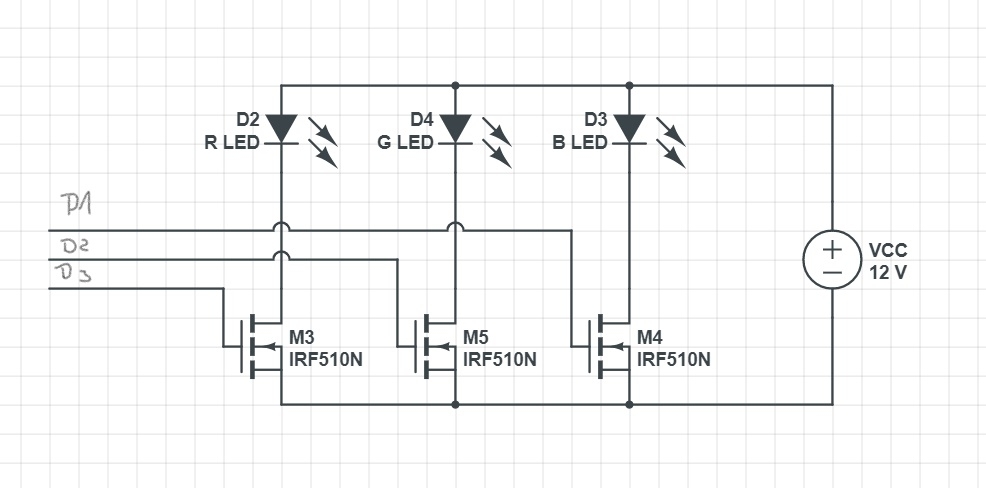
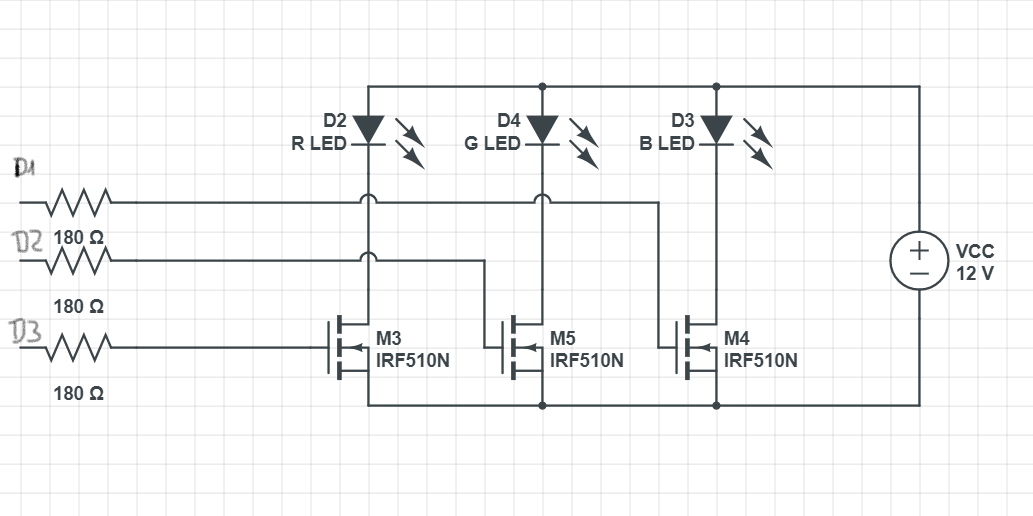
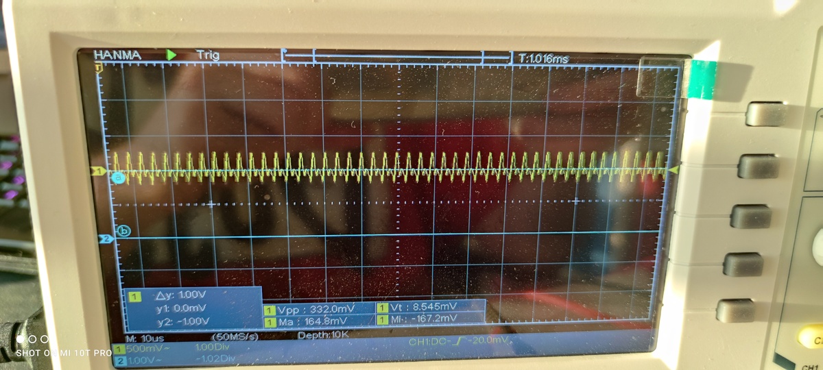
I give you the output of my oscilloscope and the different circuit
diagrams as an attachment. Maybe you have another idea or can help me
with my problem. I would be very glad.

Note: D1, D2, D3 are the signal wires leading to pin D1, D2 and D3 of my
ESP, which will output a PWM-Signal to control the mosfet.

I hope I could explain everything well.
Hey thanks for the reply. Yes it is, I have a 12v PSU from which I power
the strip and the ESP. The ESP is connected via Vin and GND to GND of
the PSU. So it shares the common ground.
What does the oscilloscope show? What are the measurement points?

Are your GND lines connected to star center as shown in the image?

The image comes from https://www.ranecommercial.com/legacy/note151.html
. This article is worth to read.
40/60 wrote:> where are the current-limting resistors for the LEDs?
Oh I'm sorry, I totally forgot it in my drawing. The resistors are
located on the LED-Strip itself. Each LED hast its individual one.
stefanus wrote:> What does the oscilloscope show? What are the measurement points?>> Are your GND lines connected to star centre as shown in the image?>> The image comes from https://www.ranecommercial.com/legacy/note151.html> . This article is worth to read.
I connected all the GND lines to the GND Terminal of the PSU.
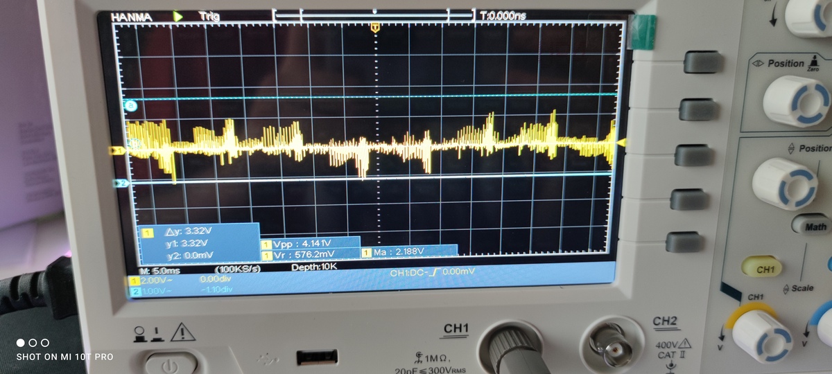
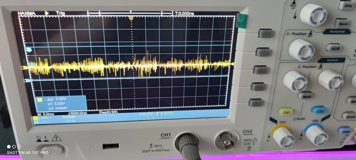
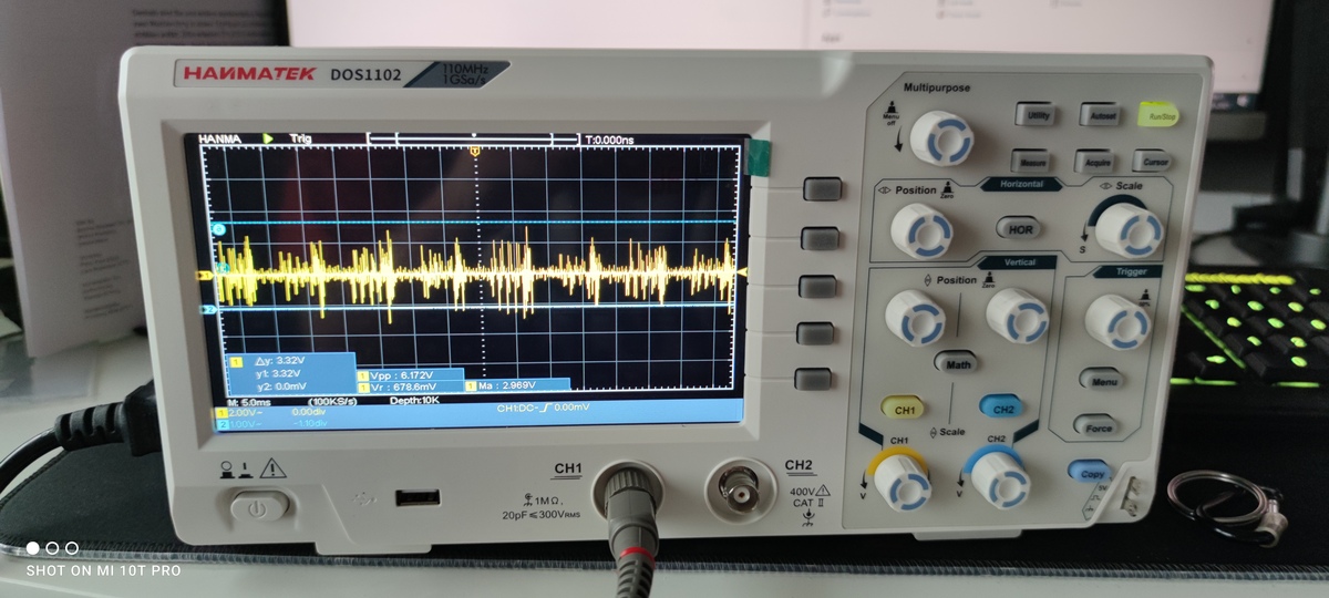
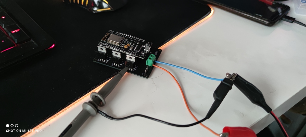
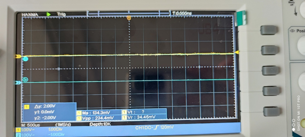
The Probes of the oscilloscope are connected to the gate of the Mosfets.
Channel one (the yellow one) is connected to the setup on my breadboard.
Channel two ( the blue one) is my soldered setup. The Probe is also
connected to the Gate pin.
For simplicity reasons, I only posted one picture, where I connected the
Osci probes to the Mosfet for the Red colour on my soldered board and on
the breadboard. I probed all of the Mosfets, to make sure its not a
single dead one, and all results look the same. Like I mentioned in my
original post, the background noise is about 1V higher on my soldered
board than on the breadboard.
Both I provide a LOW signal ob both of the Mosfets in the Oscilloscope
picture. So they should be off at this moment.
Is the switching noise at the gates still present when you turn of all 3
channels? Are you using switching mode power supplies for the LED strips
and/or the ESP? Have you applied proper decoupling/filtering for the ESP
and LED supply?
The IRF510 is also not the optimal choice for 3.3V PWM signals.
argos wrote:> Is the switching noise at the gates still present when you turn of> all 3> channels? Are you using switching mode power supplies for the LED strips> and/or the ESP? Have you applied proper decoupling/filtering for the ESP> and LED supply?> The IRF510 is also not the optimal choice for 3.3V PWM signals.
Thanks for the quick reply.
The noise does not seem to be present when I switch the Mosfet on. At
least I can not observe the characteristic I've shown you in my picture.
At the moment I'm using my lab bench power supply. What do you
specifically mean with decoupling/filtering? I've planned to place a 16v
1000uf capacitor between Vcc and GND, but I have to wait for them to
arrive. I used the last one a while ago.
Can you make a suggestion for a better Mosfet? It should be able to
handle at least 5 meters of LED strip at 12V.
I hardly wonder why you have so much noise in both circuits. Something
is going very wrong here.

Please show us an oscilloscope picture of the power supplies (3,3V and
12V).

Please show us pictures of your setup.

When you switch off an LED, does your Microcontroller output an active
LOW level or do you switch the pins into High-Z (input) mode?
stefanus wrote:> I hardly wonder why you have so much noise in both circuits.> Something> is going very wrong here.>> Please show us an oscilloscope picture of the power supplies (3,3V and> 12V).>> Please show us pictures of your setup.>> When you switch off an LED, does your Microcontroller output an active> LOW level or do you switch the pins into High-Z (input) mode?
I will post a picture tomorrow. I have to get up early tomorrow morning.
The ESP will produce the 3.3v itself. I will make you an osci picture
from my 12v supply. By pictures of my setup, do you mean my circuit or
my equipment? Or both? I control the Mosfets by supplying a PWM signal.
Wenn I switch them low, I will set analogWrite(pinR, 0 );
Fabian W. wrote:> The noise does not seem to be present when I switch the Mosfet on
Is there any noise on any of the gates when all 3 strips are turned off?
Is there any noise when you switch the strips on/off without PWM? How
long are the gate lines?
Fabian W. wrote:> What do you specifically mean with decoupling/filtering?
At least some capacitors (electrolytic+ceramic) on the supply line close
to the ESP and LEDs. The 5m strips make a formidable antenna spreading
the PWM everywhere.
Fabian W. wrote:> Can you make a suggestion for a better Mosfet? It should be able to> handle at least 5 meters of LED strip at 12V.
"5m LED strip" doesn't tell anything about the current flowing. IRLZ44N
was already suggested. FQP30N06L, FQP13N10L, IRL640A or something like
IRLML6344 or STN4NF03L in SMD. You can also do a search for logic or
super logic MOSFETS on Digikey/Mouser.
You could also keep the IRF510 and put a driver (another transistor or
an integrated FET-driver) in front of it. Before you make changes to the
MOSFETs, the problem with the noise on the gate lines needs to be
addressed.
Fabian W. wrote:> The ESP will produce the 3.3v itself. I will make you an osci picture> from my 12v supply.
And check also the 3,3V supply. With such huge problem you should not
simply trust that the bought hardware is Ok.
argos wrote:> Is there any noise on any of the gates when all 3 strips are turned off?> Is there any noise when you switch the strips on/off without PWM? How> long are the gate lines?
I tried to switch the Strip on and off manually, but with the same
result. The noise is still there.
> At least some capacitors (electrolytic+ceramic) on the supply line close> to the ESP and LEDs. The 5m strips make a formidable antenna spreading> the PWM everywhere.
I added a few capacitors to the beginning of my circuit. I switched
multiple in parallel to get a total capacity of 400uf. I don't have any
bigger ones lying around at the moment.
> "5m LED strip" doesn't tell anything about the current flowing. IRLZ44N> was already suggested. FQP30N06L, FQP13N10L, IRL640A or something like> IRLML6344 or STN4NF03L in SMD. You can also do a search for logic or> super logic MOSFETS on Digikey/Mouser.
I will definitely try that, to get the maximum out of my controller.
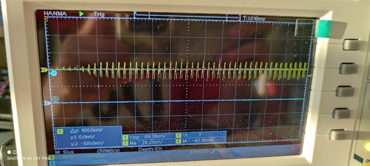
I added some pictures to this thread. I have taken a picture from my PSU
( which also outputs noise), from my setup on my breadboard, from the
LEDs manually switched on and off, and a shot with capacitors engaged.
stefanus wrote:> Fabian W. wrote:>> The ESP will produce the 3.3v itself. I will make you an osci picture>> from my 12v supply.>> And check also the 3,3V supply. With such huge problem you should not> simply trust that the bought hardware is Ok.
I probed the 3.3v regulator and could not observe any faults. It seems
to work ok.
The picture from the PSU is very very bad.

Please measure again directly at the output of the PSU (not somewhere on
your breadboard). If the noise is still visible then you should consider
to return the PSU.

Breadboards are not suitable to supply ESP modules. They have to much
resistance in their contacts. Also the Dupont wires are often thin or
made of cheap materials (not copper).

Please use soldered connections between PSU and the ESP module.

Crododile clips are also often not good enough due to their internal and
contact resistance. I took a while until I could believe that when I
discovered it the first time. You may be able to measure a significant
voltage drop between the incoming and outgoing cables that are connected
by these crocodile clips.
Just to make clear:

You main problem is that GND is not GND everywhere. You have a
significant voltage drop on the cables and connections caused by the
supply current of the ESP chip.

You can check it. Connect the GND wire of the oscilloscope to the GND
output of the power supply. Then check the voltage at any part where you
would expect GND=0V  (e.g. at the 3 transistors and at the GND input of
your ESP board).

I am pretty sure that you will see much more than 0V.
stefanus wrote:> The picture from the PSU is very very bad.>> Please measure again directly at the output of the PSU (not somewhere on> your breadboard). If the noise is still visible then you should consider> to return the PSU.
I measured directly on the terminals of the PSU and the noise was still
there. Returning the PSU is a bit late bc its my lab bench supply. I
have it for about 2 years now and never saw such a negative side effect
like now.
>> Breadboards are not suitable to supply ESP modules. They have too much> resistance in their contacts. Also, the Dupont wires are often thin or> made of cheap materials (not copper).
Maybe this is the reason, it works on the Breadboard because the
resistance of the parts is so bad, it cancels out the negative side
effects of my PSU.
>> Please use soldered connections between PSU and the ESP module.>
I will update my connections and see where this brings me.
> Crocodile clips are also often not good enough due to their internal and> contact resistance. I took a while until I could believe that when I> discovered it the first time. You may be able to measure a significant> voltage drop between the incoming and outgoing cables that are connected> by these crocodile clips.
I measured through the cables and seriously could observe a voltage
drop. I can not believe this is a thing.
stefanus wrote:> One other thing: The big electrolytic capacitor in the right lower> edge> seems to have reversed polarity.
I double checked it, and its in the right polarity. The picture is just
bad and the cap slightly turned.
stefanus wrote:> Just to make clear:>> You main problem is that GND is not GND everywhere. You have a> significant voltage drop on the cables and connections caused by the> supply current of the ESP chip.>> You can check it. Connect the GND wire of the oscilloscope to the GND> output of the power supply. Then check the voltage at any part where you> would expect GND=0V (e.g. at the 3 transistors and at the GND input of> your ESP board).>> I am pretty sure that you will see much more than 0V.
I will definitely check that.
I see where this is going. My next best guess for this problem is, to
decouple the esp from the less with a separate voltage regulator. This
could probably reduce the noise in my circuit and can lead to better
results on my gate pin. The problem is, that I can not opt for one
single PSU in later use, because I want to use this device with
different switching PSUs for a variable length of LED-Strips. Therefore
I can not guarantee that the input for my device high quality. The best
solution would be to completely decouple the esp from the rest of the
circuit, Or maybe, as you mentioned before, use a separate transistor
driver to isolate both circuits from each other.
Fabian W. wrote:> I measured directly on the terminals of the PSU and the noise was still> there. Returning the PSU is a bit late bc its my lab bench supply. I> have it for about 2 years now and never saw such a negative side effect> like now.
So it got possibly broken.
You cannot expect a working device if the power supply is already bad.
This cannot work. You have to fix that first.
Fabian W. wrote:> Maybe this is the reason, it works on the Breadboard because the> resistance of the parts is so bad, it cancels out the negative side> effects of my PSU.
Yes that sounds like a good explanation.
Fabian W. wrote:> I see where this is going. My next best guess for this problem is, to> decouple the esp from the less with a separate voltage regulator.
It has already an own voltage regulator on the board.
Ensure that GND ist 0V everywhere and fix the power supply. Then it will
surely work.
Fabian W. wrote:> I measured directly on the terminals of the PSU and the noise was still> there.
The noise from the power supply is awful. Instead of an additional
voltage regulator, you could try a simple RC filter in the supply line
of the ESP.
argos wrote:> Fabian W. wrote:>> I measured directly on the terminals of the PSU and the noise was still>> there.>> The noise from the power supply is awful. Instead of an additional> voltage regulator, you could try a simple RC filter in the supply line> of the ESP.
OK. I will first have to read a bit about RC filters. I've never built
one. But I will definitely try it with that.
argos wrote:> Fabian W. wrote:>> I measured directly on the terminals of the PSU and the noise was still>> there.>> The noise from the power supply is awful. Instead of an additional> voltage regulator, you could try a simple RC filter in the supply line> of the ESP.
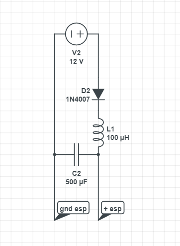
Ok. I came up with this circuit. It reduced the noise drastically. I
mean it works, but I'm not sure, if this is the right approach. Maybe
you can tell me if this is the right way to do it. I probed the circuit
with my oscilloscope, and it seemed fine.
As I said, I'm not totally into this topic yet.
I would be glad for any advice.
stefanus wrote:> The right way is, to fix the problem at its source, which is your> PSU.
I did understand what you Sayed. Nevertheless this isn't an option at
the moment, because this is for test purposes. I do not know which psu
I will use later on in my build. It could be, that the psu is better
than this one. It also could be that it is equal or worse, I don't know
yet , because I haven't bought it yet. The thing I want to do now is
making my circuit bullet proof against this kind of problems. Therefore
I want to know if the circuit I made is sufficient for that. I know that
I have to switch the PSU but that is not a thing for today.
Is the circuit I made ok as rc filter ?
Fabian W. wrote:> Is the circuit I made ok as rc filter ?
You measured already that the filter works fine, so I wonder why you
ask. I cannot say that this is a good solution.
It is a workaound.
Fabian W. wrote:> Ok. I came up with this circuit. It reduced the noise drastically. I> mean it works, but I'm not sure, if this is the right approach.
Yes, a LC-Filter is fine too. Keep in mind that with a working PSU you
wouldn't need a filter at all. Are the gate voltages now clean and the
LED strips working as expected?
argos wrote:> Fabian W. wrote:>> Ok. I came up with this circuit. It reduced the noise drastically. I>> mean it works, but I'm not sure, if this is the right approach.>> Yes, a LC-Filter is fine too. Keep in mind that with a working PSU you> wouldn't need a filter at all. Are the gate voltages now clean and the> LED strips working as expected?
Sorry that I couldn't answer earlier. I connected an improved version of
my input filter and now have a very clean output voltage.
The only problem now is, that the random LED flicker is still there. I
measured the Gate pin of my transistor, and I can not observe anything
suspicious. NO RIppeling, no weird current spikes. Only thing I have is
a random "Noise" of about 17mv peak to peak. But I think this could be
ignored, since the voltage is so small, it should have no effect on the
transistor. Since I solved my PSU issue with my input filter I have no
idea what could cause this flickering behaviour.
Fabian W. wrote:> The only problem now is, that the random LED flicker is still there.
Flickering while the LED-strips are on? Have you tried using the cleaned
up voltage not just for the ESP but also the strips?
The LEDs flicker only when they are off. When I turn them on, they are
stable. I just tried it, but i can not observe any flickering during on
time. I conected my input filter to my esp and my Led with the same
result.
Fabian W. wrote:> The LEDs flicker only when they are off.
There must be a reason why the transistor switches on.
Measure the voltage between Gate and Source of the transistor with your
oscilloscope. You may use its trigger function to catch the moment where
an unexpected voltage occurs. Also measure the voltage between Source
and GND of the microcontroller (should be 0).
stefanus wrote:>> There must be a reason why the transistor switches on.>> Measure the voltage between Gate and Source of the transistor with your> oscilloscope. You may use its trigger function to catch the moment where> an unexpected voltage occurs. Also measure the voltage between Source> and GND of the microcontroller (should be 0).
As you tole me, I measured between source and gate of the transistor.
When I connect the GND side of my probe to source and the probe itself
to the gate pin, nothing happens very much. I get some low background
noise of around 12 -30 mv. Nothing that should trigger the transistor.
However if I swap the probes and connect my probe side to source and the
gnd side of the probe to the gate pin, I have frequent pulses of about
300mv. I don't know why that's so different. I checked my Gnd with the
Source pin of the transistor and it is about 0v.
By the way, my new transistors arrived. The ones that were suggested in
this thread. I will try them out shortly and report if this changes
something.
Fabian W. wrote:> However if I swap the probes and connect my probe side to source and the> gnd side of the probe to the gate pin, I have frequent pulses of about> 300mv. I don't know why that's so different.
That is wrong usage of your device.
You connected the shield of the cable and the internal shield of your
oscilloscope to the gate. The amount of metal can recieve a lot of
interference from radio signals.
The same happens when you touch an analog input of a HiFi system or an
active speaker with your finger. Your whole body received radio waves.
Therefore the shield of your oscilloscope should be grounded as well as
the shield of your ESP module and your power supply. And here it is
important that all the GND wires have a low DC resistance and low AC
impedance. A loop of a half turn is already critical for such high
frequencies as your ESP module operates on.
The more important test was to check whether there is a voltage drop
between the GND pin of your ESP8266 and the source pins of your
transistors. You did not answer this question.
> I checked my Gnd with the Source pin of the transistor and it is about 0v.

Not sure where you measured this. But GND should be GND (equals 0 Volt)
everywhere. You have possibly bad GND connections caused by

- thin wires
- long wires
- weak connections (breadboard contacts, or vias between PCB layers)
- loops in wires or printed lines

Do not forget that even a line with a half turn around the PCB is
already a significant coil for such high frequencies.
Next time, please post detailles photos from your equipment and PCB and
make a drawing where you connected your oscilloscope. It makes really a
big difference where exactly you connected it even if all possible pints
are connected to each other by a line.
 oszi.jpg
(240 KB)
oszi.jpg
(240 KB)
 With_ResGtoS.png
(25 KB)
With_ResGtoS.png
(25 KB)
 WithoutRes_LI.jpg
(91 KB)
WithoutRes_LI.jpg
(91 KB)
 WithResBoth.png
(32 KB)
WithResBoth.png
(32 KB)
 WithResSignal.png
(29 KB)
WithResSignal.png
(29 KB)