LowPassFilter using OpAmp

OP #7876911
Rate this post
useful
not useful

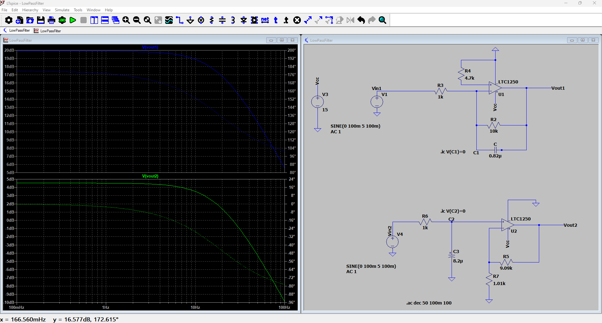
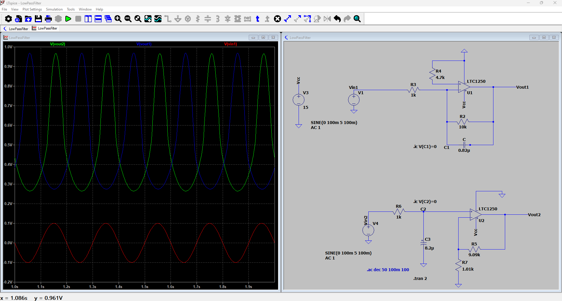
Hello µC community, I'm using LTspice to design a low-pass filter using an OpAmp. However, I've encountered an issue where the amplitude outputs u1 and u2 are equal, despite their intended 10x amplification. The second picture illustrates that the frequency response of OpAmp U1 and U2 are not the same. I'm seeking assistance to understand this result better. Any insights or explanations would be greatly appreciated. Thank you!

Attached files:
#7877442
Rate this post
useful
not useful

Ahmad K. wrote:

"for single supply by biasing the (+)-input of the op amp with Vcc/2." I don't understand what do you mean in this sentence

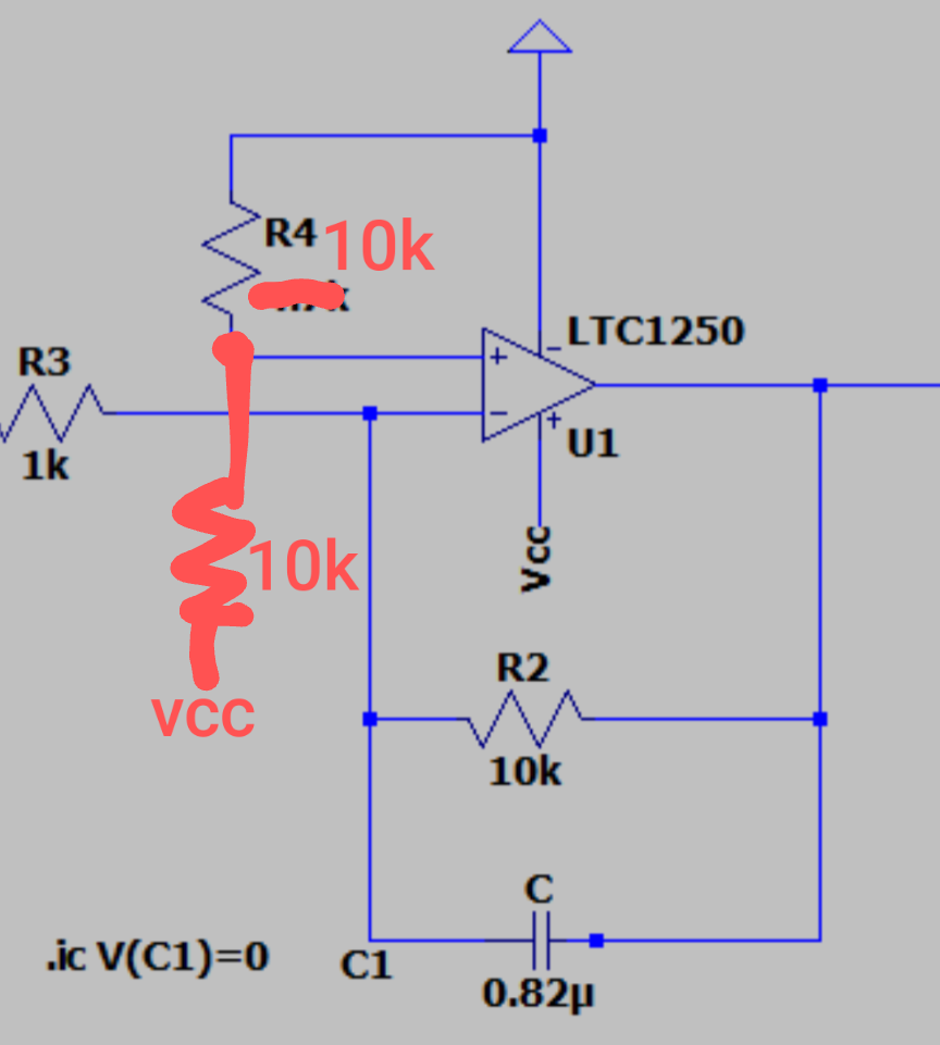
That means, with single supply, the (+)-input of the op amp cannot be connected directly to GND (= 0 V). You have to apply Vcc/2 (= 7.5 V) instead. Don't forget to AC couple the source V1 (and eventually the load).

OP #7877488
Rate this post
useful
not useful

Robert M. wrote:

Ahmad K. wrote:

"for single supply by biasing the (+)-input of the op amp with Vcc/2." I don't understand what do you mean in this sentence

That means, with single supply, the (+)-input of the op amp cannot be connected directly to GND (= 0 V). You have to apply Vcc/2 (= 7.5 V) instead. Don't forget to AC couple the source V1 (and eventually the load).

Robert!! Why should i connect half vcc to the non inverting pin.. The circuit works perfectly.

My question is why is difference between frequency response for these circuits diagram nevertheless the amplification in output is the same

#7877666
Rate this post
useful
not useful

Ahmad K. wrote:

The circuit works perfectly.

Your own plots tell a different story. Gain factors do not match and output voltages are completely distorted. That's the exact opposite of perfect.

You apply a +/-100 mV peak AC voltage at the input. When the voltage is at +100mV peak, the output of the inverting amplifier would have to go to -1 V peak. Same thing would have to happen with the non-inverting amplifier when the input voltage is at -100 mV peak. That is impossible with single supply.

The inverting amplifier has a few additional flaws. The LTC1250 is a low 1/f noise, zero-drift amplifier. Trying to cancel the effect of bias current with R4 doesn't work the same as with other generic op amps. In reality you make it worse by using R4 at all.

The op amp has an internal nulling circuit that's using the external resistor R2 to close the loop. The loop needs a certain bandwidth (at least 7 kHz) to work. You are impeding that by lowering the bandwidth to ~20 Hz because of C= 820 nF across R2, which in turn results in an increase of 1/f noise and offset voltage.

OP #7881927
Rate this post
useful
not useful

Robert M. wrote:

Ahmad K. wrote:

The circuit works perfectly.

The inverting amplifier has a few additional flaws. The LTC1250 is a low 1/f noise, zero-drift amplifier. Trying to cancel the effect of bias current with R4 doesn't work the same as with other generic op amps. In reality you make it worse by using R4 at all.

The op amp has an internal nulling circuit that's using the external resistor R2 to close the loop. The loop needs a certain bandwidth (at least 7 kHz) to work. You are impeding that by lowering the bandwidth to ~20 Hz because of C= 820 nF across R2, which in turn results in an increase of 1/f noise and offset voltage.

Thanks Robert I got it :-))

Reply

Please log in before posting.

or

Log in with Google account

Registration is free and takes only a minute.

Register now