Half bridge motor controller

#7688451
Rate this post
useful
not useful

Hi everyone,

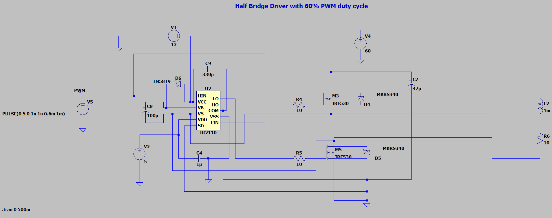
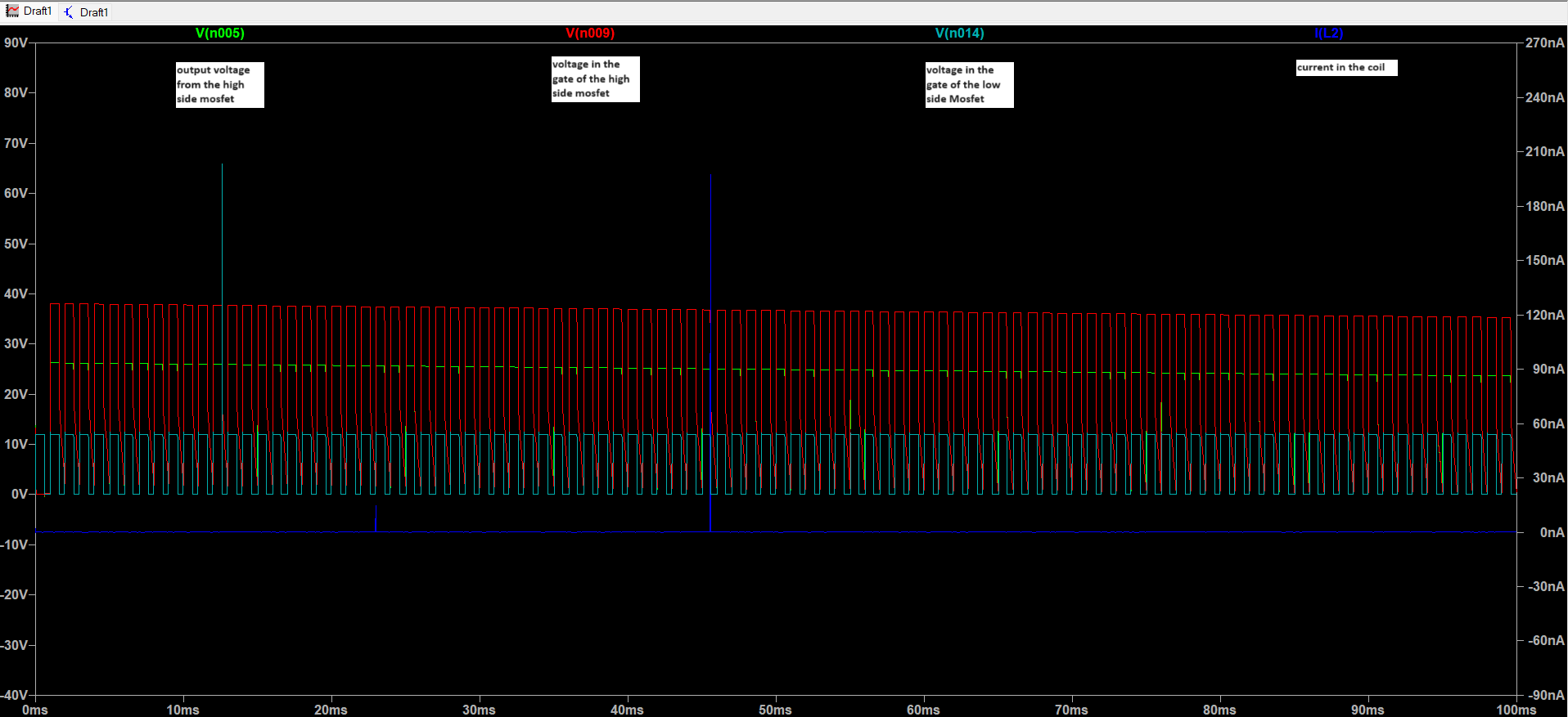
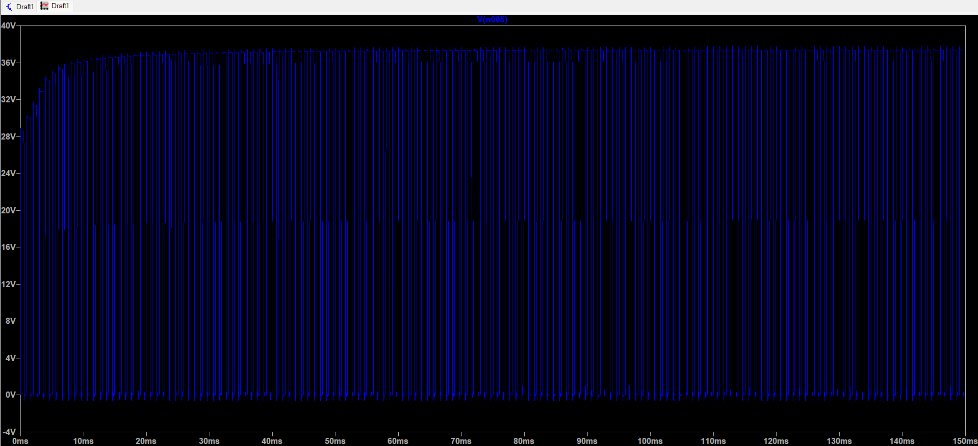
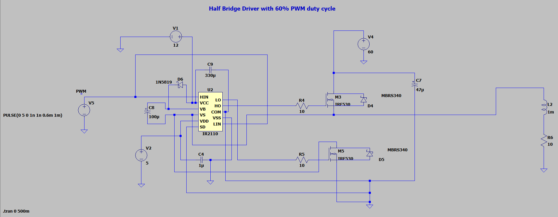
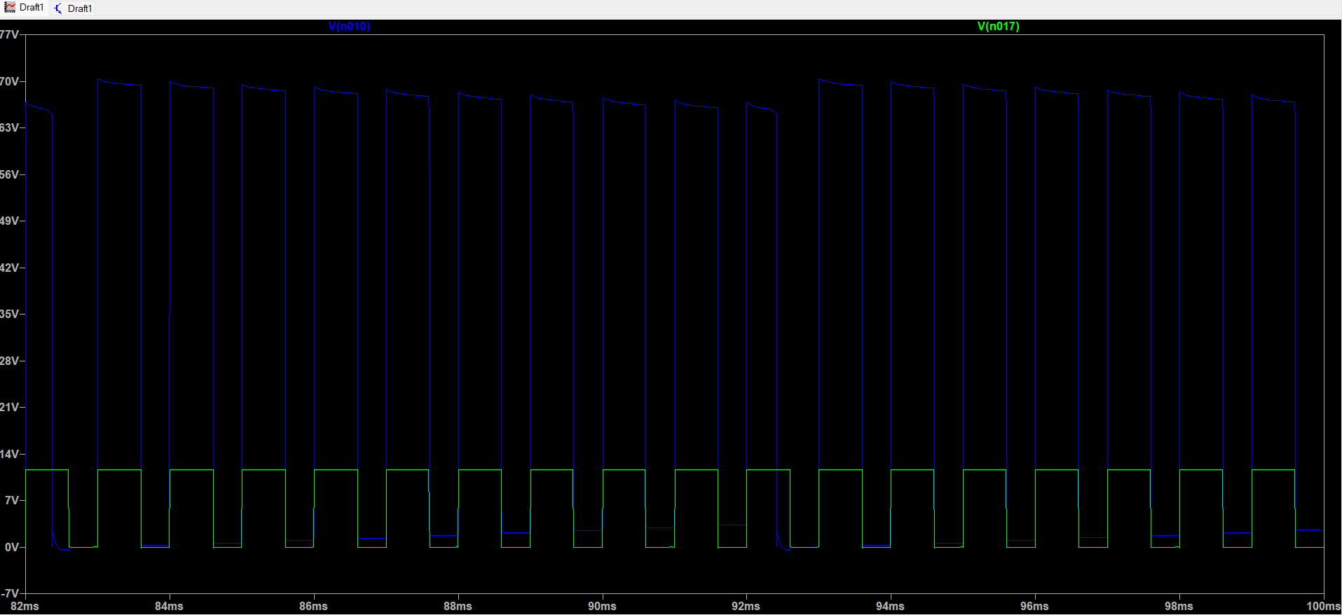
I am trying to simulate in LTspice a half-bridge 60V motor controller with a 60% PWM signal. While simulating, I noticed that the voltage and current appear abnormal. I have attached some screenshots and the file.

Any help would be greatly appreciated.

Thank you!

Attached files:
#7688485
Rate this post
useful
not useful

Anna schrieb:

I noticed that the voltage and current appear abnormal

Looks ok.

The first high doesn't come through because the boost capacitor had no time to charge.

The voltage decreases slowly because your pwm is too fast for the MOSFETs.

The current stays at 0 because if you either turn on the lower OR turn on the high side MOSFET there is never a closed circuit.

Probably the motor coil should go to GND and the half bridge may act as an synchronous rectifier.

#7689212
Rate this post
useful
not useful

Hi Michael,

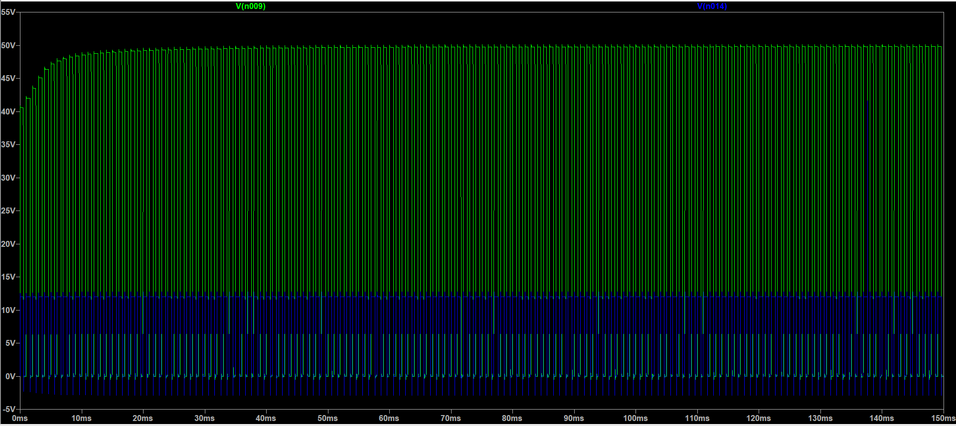
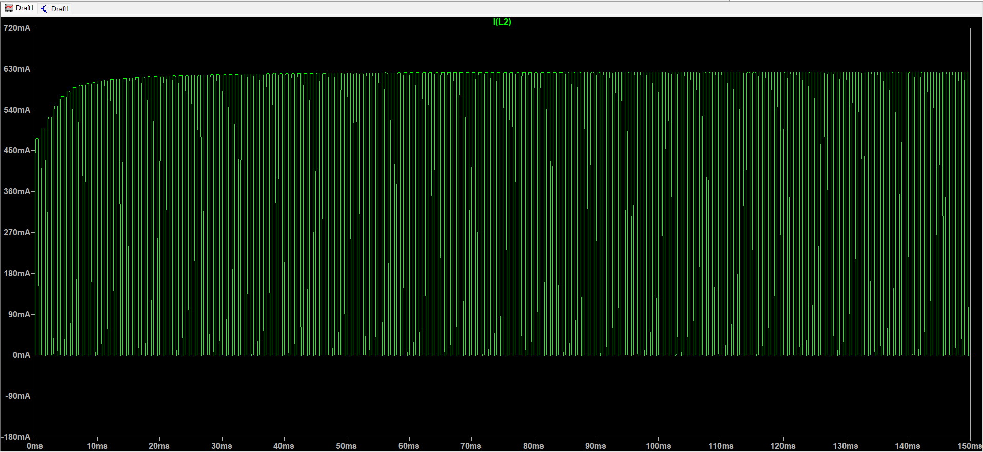
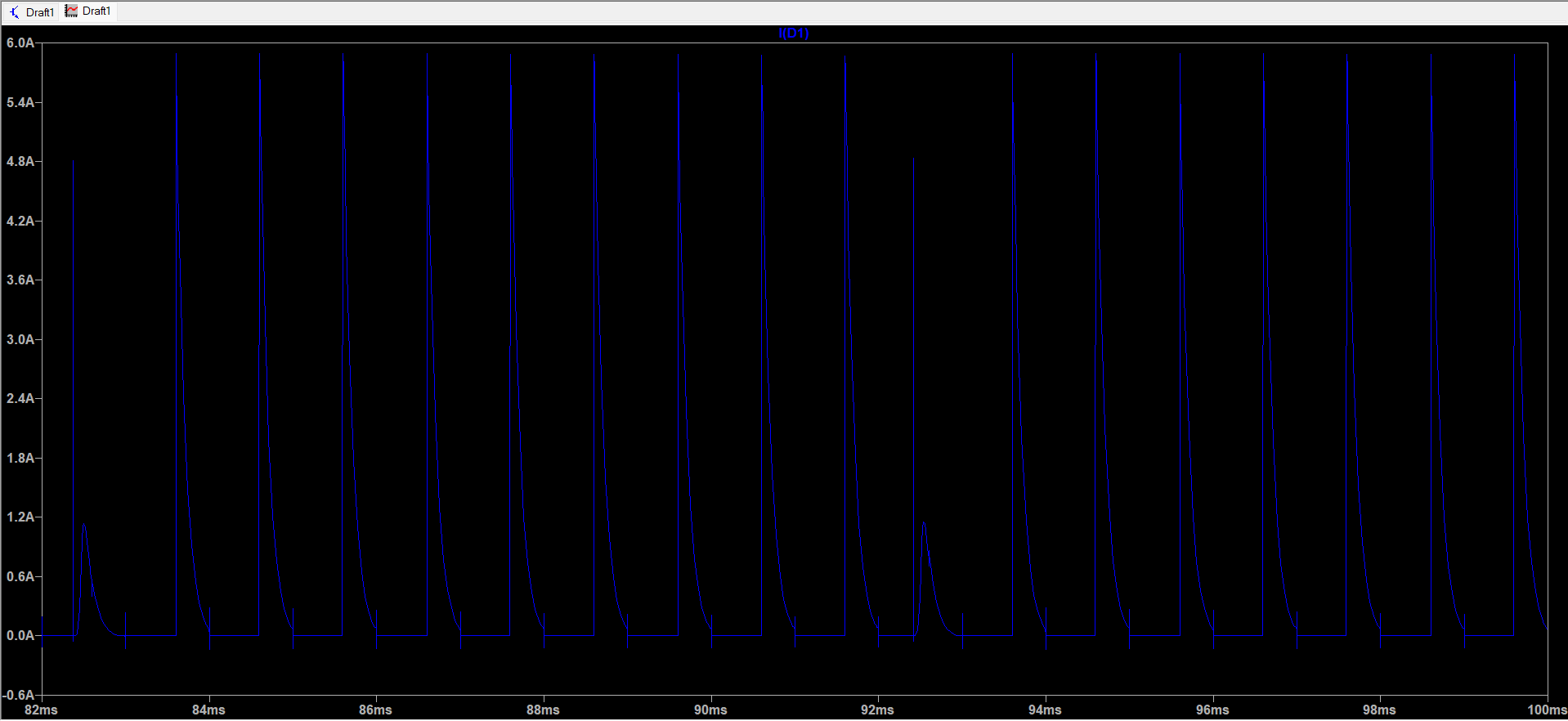
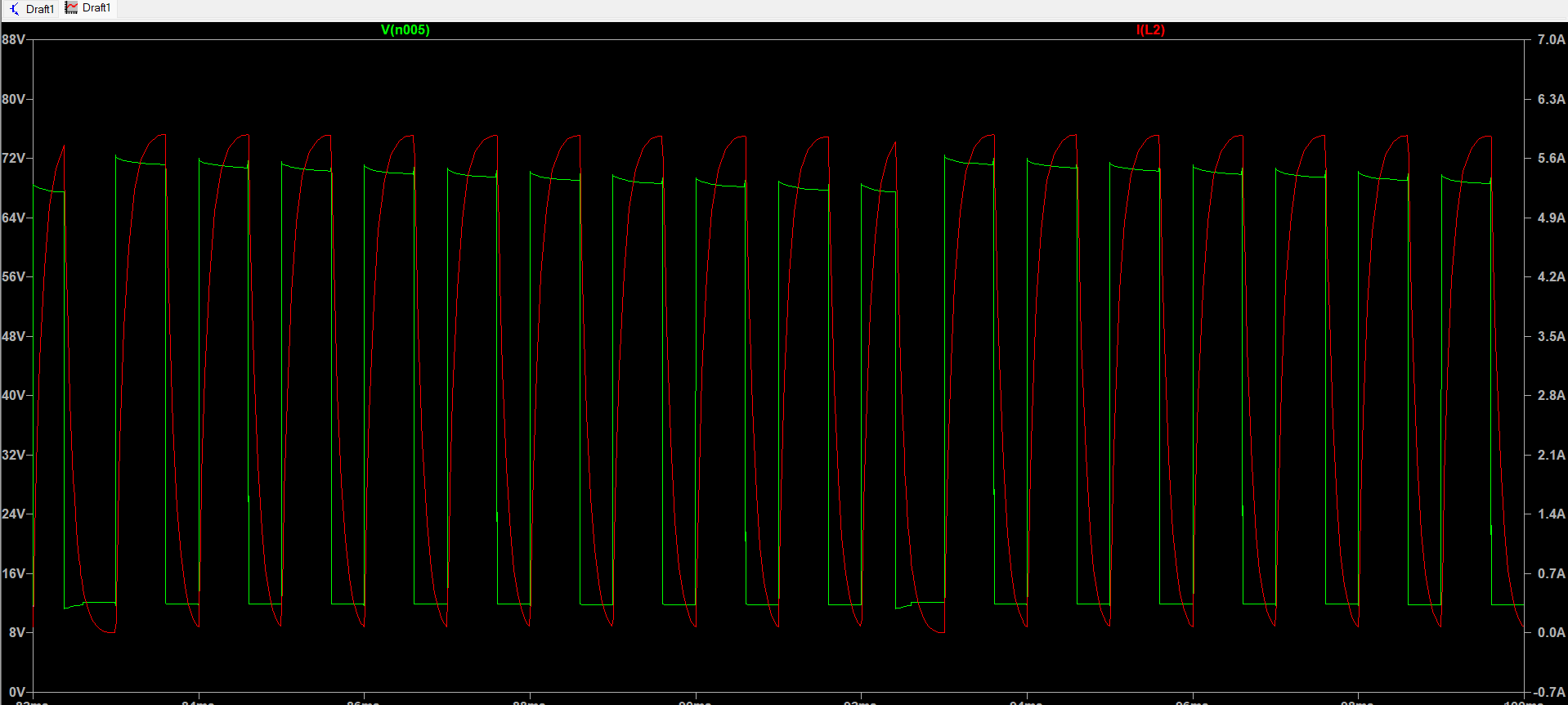
Thank you so much for your support. I connected the motor coil to GND as you mentioned, and the simulation has improved :) However, I think the current is still too low to drive a 60V 10A motor. Also, the voltage at the gate of the low side MOSFET is 12V, which I think should be higher. You can find the new simulation attached for further clarification.

Thank you again for your time and support!

Attached files:
#7691407
Rate this post
useful
not useful

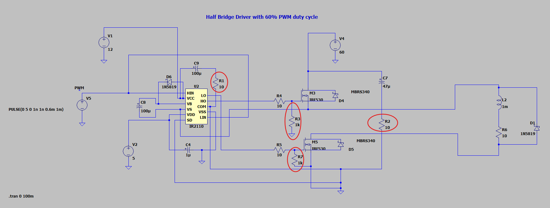
Hi everyone, I tried to simulate the circuit, but the output voltage and current waveforms in the coil do not appear ideal. I added a freewheeling diode parallel to the load and some resistors on the gates to discharge the gate capacitance, but it seems insufficient. I am a student and would greatly appreciate your explanations and support regarding this issue. If you have any solutions or recommendations, please feel free to share them with me. Thank you so much! Attached are the circuit and simulation.

#7691463
Rate this post
useful
not useful

Anna schrieb:

I tried to simulate the circuit

You didn't understand anything.

The IR2110 can not operate (close) the high side MOSFET at the same time as the low side MOSFET as it requires the low side MOSFET to charge the boost capacitor in the off time of the high side MOSFET by connecting VS to GND.

You can only operate one MOSFET to PWM the motor voltage and may use the other for active frewheeling.

It is 100% sufficient to switch just one power connection of the motor, there is no need to break both.

#7692005
Rate this post
useful
not useful

Michael B. wrote:

The IR2110 can not operate (close) the high side MOSFET at the same time as the low side MOSFET as it requires the low side MOSFET to charge the boost capacitor in the off time of the high side MOSFET by connecting VS to GND.

I tried to direct the focus of the TO to this already on 20th of June but it was ignored. The circuit will never operate properly with LIN and HIN driven by the same signal.

Reply

Please log in before posting.

or

Log in with Google account

Registration is free and takes only a minute.

Register now