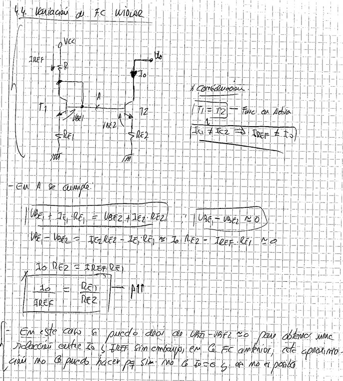
Hello.

My problem is that I dont know if there is any IC which can amplifies
low current with a very low noise. I need to amplify the low current
generated by an photovoltaic detector (around nA) to something bigger
(around uA). And i can't use a transductor amplifier....

I was thinking about a mirror courrent source with the WIDLAR
strucuture. But I don't know which trt't use in order to achive a
properly working with nA current (See doc. attached)...Can you give me
some advise?

Thank you very much for your help!

B.R.

Enrique P.
Attached files:
-

kk.jpg
280 KB
Der Stromspiegel wird nicht gut funktionieren. Da ist einfach das
Rauschen und die Drift vergleichsweise hoch.

Was ist das Problem mit dem Transimpedanzverstärker ?
Da gibt es ggf. Varianten auch für spezielle Fälle.

Um welche Frequenzen geht es ?


I really don't think you really consider a transductor (magnetic
amplifier) based amplifier. A agree that that would be a rather bad
choice - though it has some interesting points.
Attached files:
-

Unbenannt.png
4.9 KB
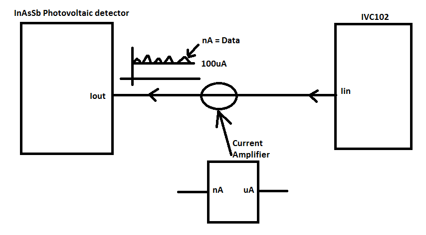
Hello.

first of all thank you so much for your answer.

Regarding the question. we want to take measurements in ms. So the
maximum freq could be 300KHz.

At the output of the photodiode we have already a switched integrator
transimpedance amplifier: IVC102. And we need to use this IC because it
provides a reset circuit (which only works with current) for reseting
the photo diode. Take a look to the picture attached.

The main problem of IVC102 is the low sensitivity (uA). The photodiode
gives the information in nA and IVC102 would not detect so small
variations of current.

So then my question is how to amplify the output current of the photo
diode to be detected by the IVC102 IC?

thank you so much.
Keithley has published a low-level measurement handbook where they
discuss some measurement principles for picoampere measurement. Maybe
you can get some ideas from that handbook. Available for free on the web
or from Keithley.
As I know, photodiodes also work with very low current output.
Maybe you get some information using GOOGLE
  "nA" "photodiode" current "amplifier"
Yours
The IVC102 is alleady quite good in working with very small currents.
It's actually quite hard to make it better. So nA currents should not be
a problem. With 10 pF capacitance 1 ms at 1 nA allready gives 0.1 V
change at the output.

So the points would be to make the IVC102 work well: keep the
temperature down and the supply voltage very clean und HF signals out.
Also a very clean circuit is important, and avoid cables as much as
possible. Maybe there are slighly better suited (or graded) versions
available (e.g. only one capacitor, ceramik case).

One can get more current likely easier by using a larger detector or
even better optical concentration (lense, mirror).
Enrique Perez wrote:
> And we need to use this IC because it
> provides a reset circuit (which only works with current) for reseting
> the photo diode.

I dont understand what the IC does, but whatever, it will not function
backwards through the Current Amplifier. If it is true what you say you
have to use the IVC102 as the first stage.

sy Reinhard
Attached files:
-

kk3.png
4.6 KB
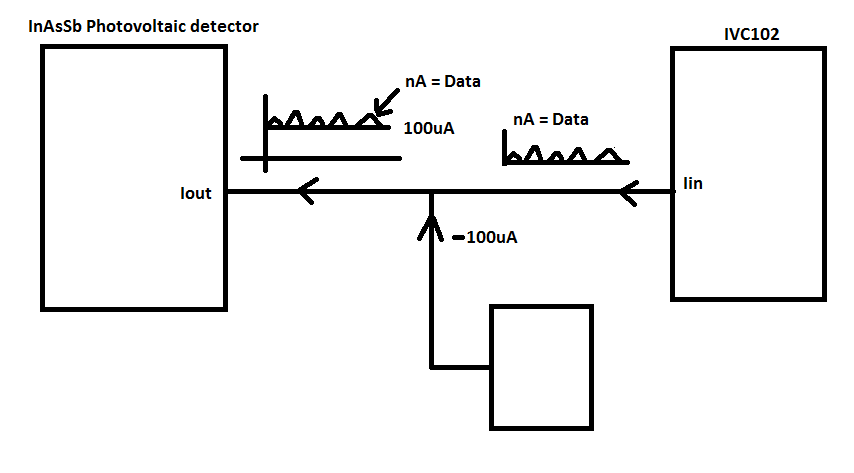
yes I need to use the IVC102 like the first stage. And reading carefully
the datasheet of this IC. I figured out that it is possible to control
the gain with an external cap. So I don't already need a previus
amplification stage. The IVC102 is able to amplify low currents.

But now I need to compensate the dark current of the photodiode. it
provides a offset current around 100 uA. And the max input current for
the IVC102 is also 100uA. So the IVC102 could be damaged. I was thinking
to remove this offset dark current using a digital potenciometer (see
picture attached) But I am open for other low noise solutions...Any
idea?

Thanks.
So you have a signal in the nA-range, but a dark-current of 100µA, which
is "just" 100000 times bigger and even exceeds your amplifier input
range?

Then I would recommend you to find a way to modulate your fotocurrent
(i.e. a chopper in front of your detector). Amplify your signal with a
standard transimpedance amplifier, which can handle the 100µA dark
current and the modulation frequency. (the IVC102 is an integrating
ampflifier and will probably be to slow to follow the modulation of the
signal). And then let a lockin-amplifier take care about filtering the
(modulated) signal from the background and noise.
A current of 100 µA won't damage the IVC102, but just saturate it. With
an extra capacitor it may be possible to use larger currents - still a
large background current makes interpreting the output difficult. Such a
current is also accompanied with a significant amount of noise. So the
best would be to get to reduce background light as much as possible.

To get a low noise current to compensate for the background, one can use
a rather large resistor (metal film, not carbon or semiconductor e.g.
near 100 K) and a well stabilized/filtered voltage. To adjust the
voltage and thus the current a digital pot is possible before filtering,
after a good ref. source.

It is reasonably easy to get the noise of the current lower than the
inherent noise due to the background photo-current. So reducing this
current may be essential.
If this is really background light, there may be extra variations in the
light, and second photo-diode to measure the background may be a good
idea.
Yes Ulrich, you are in the right direction.

In a first instance we are able to keep the dark current to 100uA always
with a temp of -60ºC. Now I was thinking to use a high quality digi pot
like x9118tv14z-2.7 to compensate the dark current. But I was wondering
what do you mean when you say "rather large resistor (metal film, not
carbon or semiconductor e.g. near 100 K) and a well stabilized/filtered
voltage".
If you use this pot: x9118tv14z-2.7, Is it also neccesary to use the
large resistor that you say? For sure that I am able to provide a well
stabilized/filtered ref. voltage for this pot....

Thanks.
It depends on the type of digital pot, but usually they have more noise
than a resistor made from metal. So it is better to have the metal (at
the high values metal film) resistor and a low noise voltage. To get a
low noise variable voltage, a good (especially low frequency noise) ref
source, a D/A convert or digital poti and a filter is the usual way. So
any noise from the D/A or digital pot an  reference is filtered first.

It may work with just a voltage and the digital pot, as the requirements
are not so very high (the noise of the diode bias is already quite high)
- but a metal film resistor in the 100 KOhms range is a rather cheap
thing, so why take chances for just a few cents.

What type of detektor is this, that it needs cooling to -60 C to get 100
µA dark current ? Must be rather large or infrared i guess. Dark current
also depends on the bias voltage - often a compromise between dark
current and speed / capacitance related noise. So you may have to
recalculate that choice.
Attached files:
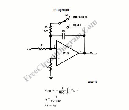
Hello again!

Thank you for you advise I will use a metal resistor compensate the dark
current.

Yes. It a detector manufactured by Hamamatsu and it is an experimental
detector...

On the other hand I would like to have another option in my prototype,
because could be that the IVC102 won't work in the way I would like.
Then I was thinking to set up my own reset circuit + transimpedance Amp.
I mean i would like to design something like the picture attached

But the main problem of this circuit is to find a good switch with low
noise and good characterisitics...

Any advise?

Thanks
The switch really is a difficult part, because it needs to have low
charge injection and low leakage. However a very low resistance in not
needed - this could be in the 100 Ohms range. The obvious choice is a
CMOS switch. Against leakage it may be possible to use 3 switches in T
form: 2 in series and one to ground, so that the last switch will be
between the input and quasi- GND if off. So charge injection is the
really critical parameter.

With the rather large current from the detector the circuit is not that
critical as in original IVC102. Likely that capacitor will be larger and
the amplifier may be lower noise and faster, even if this would mean
more leakage current. So the requirements for the switch may be less
stringent.

I don't have an advice on a special part - just look at the
manufacutures (e.g. LTC, AD, Ti, Maxim) websites.

An alternative may be using a photomos switsch, though I don't know
exactly how good they really are. Also 2 JFETs may be possible, one as a
switch and one to compensate.
Thank you so much ulrich for your advise. I was taking a look and this
kind of switches seems to be good: ADG821.

They have low noise and combained with a good transimpediance OA could
give good results.

On the other hand there is another switched integretor + reset IC very
similar to IVC102 that but with a lower input offset voltage. This part
is ACF2101.

I will try several options in my prototype and then I will see which is
the best...

Thanks!
The ADG821 is a good switch for some applications that need a low
resistance, bud a really bad choice for such an integrator for small
currents. Low noise may be important with the amplifier, but low bias is
also important.

Something like a ADG1201 or ADG202 would be more suitable, though charge
injection is still much worse (at least guaranteed over full range) than
in the IVC102.
Right the switch ADG1201 is really a better option. I will try with this
and the I will tell you something.

Thanks!
Please log in before posting. Registration is free and takes only a minute.
Existing account
Do you have a Google/GoogleMail account? No registration required!
Log in with Google account
Log in with Google account
No account? Register here.