Guest
#6964063
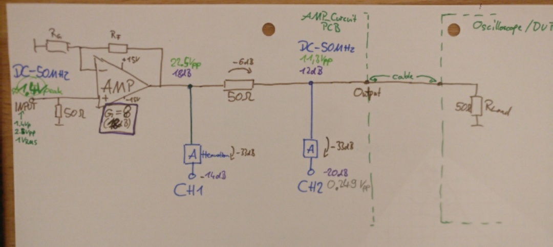
Hi, I want to rebuild a amplifier that Amplifies a 2.8Vpp DC-50MHZ
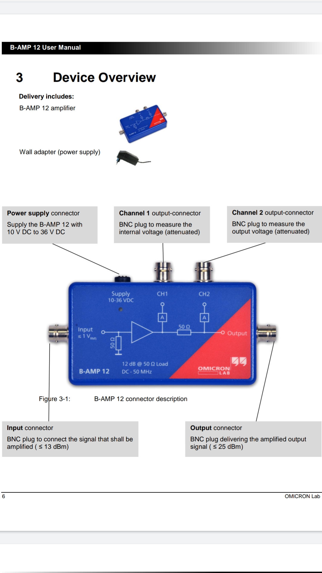
Signal. The Output should be 12dB (11,3Vpp) as in the technical
Datasheet mentioned. So far so good, it works with the THS3491 (right on
the edge, but it works in the simulation.

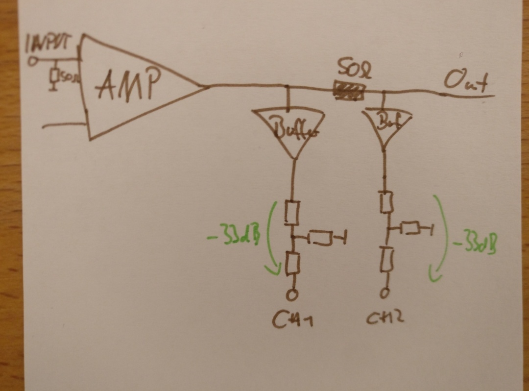
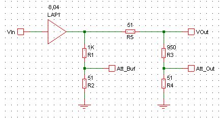
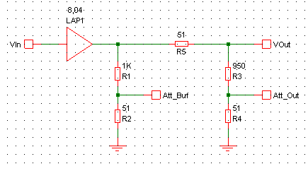
Now I want to design the Attenuation on CH1 and CH2. It attenuate 33dB.
Problem I have with this is, that the Attenuation build a Voltage
Divider with a T/Pi Attenuator and the 50 Ohm&also the 50 Ohm Load. It
changes my Output Voltage..

How can I make that the CH1&CH2 Path (for measuring internal and output
Voltage) don't change my Voltage? I thought that I could use a Buffer,
than the Input is high impedance. But I couldn't find any Buffer that
works with 0.1dB flatness at 50MHz and also the Input would be 22.5Vpp
on the one at CH1..

How would you tackle this?

Datasheet of Reference Design I want to build:
https://www.omicron-lab.com/products/vector-network-analysis/accessories/b-amp-12-amplifier

Thanks
Attached files:
-
 Screenshot_20220202-225322__01__01.jpg
(100 KB)
Screenshot_20220202-225322__01__01.jpg
(100 KB)
-
 Screenshot_20220202-225326__01.jpg
(140 KB)
Screenshot_20220202-225326__01.jpg
(140 KB)
-
 Screenshot_20220202-224848.jpg
(400 KB)
Screenshot_20220202-224848.jpg
(400 KB)