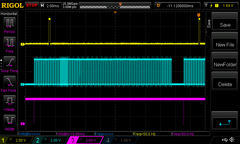
Hey guys!

After a little bit of doubt (I don't have much experience using fpga's)
I decided to post my question here...

I have a retro computer that I'd like to RGB mod by using an IC40 HX8K.

I have been experimenting quite a bit and have done the following:

- Mapped out the original color PROMS of the system so I have all known
input and corresponding output bits.
- Scoped out the internally created sync to measure front porch, back
porch etc. Basically mapped out all the timings.
- Found out that serration pulses are missing in the internally created
Csync signal, making this signal unusable since it will not work with
some tv's or scalers.

After this I started using Verilog to code and experiment. I use
Icestudio to create codeblocks. I thought to start with modeling a piece
of ROM that mimics the original PROM of the computer to output the RGB
pixel data from my fpga. This works fine and I am confident that what I
see on my scope as output from the fpga is corresponding to the data the
computer outputs to form pixels on the screen. From this I conclude that
my RGB pixel output is correct and my modeled ROM is creating pixel data
the way the original PROM does.

I then proceded to create an appropriate sync signal with correct
timings. This was not super difficult since I had all the timings scoped
out already. As a template I used one of the many VGA controller
tutorials available online and I adapted this for my needs. When I
review my work on my scope I can see a csync signal that corresponds to
the timings that I need.

Now... I am feeding the system clock (4Mhz) to the modeled ROM and also
use it as a way to creat sync, both modules (modeled ROM and sync
creation) are on thesame clock. The thing is that when I review my
signals on my scope I find that there is a random time difference
between sync signal and my pixel data on every power-up or reset.

When I power-up the systemp I always have sync ahead or behind the pixel
data. It never matches up and it is never thesame amount of time-shift.
I added a picture of my scope which shows Vsync in yellow and pixel data
in blue for reference. As you can see... Vsync is ahead.

I was wondering whether my general approach is ok, or if should use a
different one. I have thought about creating a signal with a pulse that
triggers the sync counter at the right time. I have been able to create
that signal out of the pixel data, as is shown in my added picture in
purple. The rising edge of this tiny little negative pulse matches up
exactely with the position where Vsync is supposed to be, but I am
unable to actualy make sync start in that location.

I was just wondering what it could be that makes for this time
difference. I find all sorts of guides on creating Sync and pixel data
inside an fpga, but there seems to be almost no documentation (at least
not that I can find) on how to bring a pixel bus from an external system
into an fpga and recreate a sync signal with the systems clock to
accompany it.

If my question seems like a beginners one or if I have not provided
enough information then let me know. I was just wondering where the time
difference could come from, and if I am approaching this project in the
right way, or if I should go about it in a completely different
approach.

To anyone who made it this far... thanks for reading! :-)
Attached files:
-

b.png
14 KB
Alright, so some code. Here is the part I use to model the color PROM of
the original machine. I also use D4 (it's a 5 bit address bus I'm
tapping into) to create a startpulse for sync. The timing of this
startpulse is locked on to the output rgb data and so it creates the
purple negative pulse as show in my opening post. I was wondering if I
could use this as some sort of sync enable/start pulse.

Icestudio lets you create any inputs and outputs visually so I don't
code these.
1 | //-- COLOR ROM memory
|
2 | reg [2:0] red_rom [16:0]; |
3 | reg [2:0] green_rom [16:0]; |
4 | reg [2:0] blue_rom [16:0]; |
5 | |
6 | //-- RGB pixel buses (3 bits)
|
7 | reg [2:0] RED; |
8 | reg [2:0] GREEN; |
9 | reg [2:0] BLUE; |
10 | |
11 | //-- Address bus (5 bits)
|
12 | wire [4:0] A; |
13 | |
14 | //-- Synchronize CS to data
|
15 | reg startpulse; |
16 | reg [12:0] countD4; |
17 | |
18 | |
19 | //counter while D4 is high
|
20 | always @ (posedge clk) |
21 | begin
|
22 | if (A[4] <= 0) |
23 | countD4 = 0; |
24 | else
|
25 | countD4 = countD4 + 1; |
26 | end
|
27 | |
28 | //position of sync pulse start (use as EN signal for sync?)
|
29 | always @ (posedge clk) |
30 | begin
|
31 | if (countD4 == 6399) |
32 | startpulse <= 1; |
33 | else
|
34 | startpulse <= 0; |
35 | end
|
36 | |
37 | |
38 | always @(posedge clk) |
39 | begin
|
40 | RED [2:0] <= red_rom[A]; |
41 | GREEN [2:0] <= green_rom[A]; |
42 | BLUE [2:0] <= blue_rom[A]; |
43 | end
|
44 | |
45 | |
46 | //-- Memory contents read from the ROMFILE file
|
47 | initial begin |
48 | if (R) $readmemb(R, red_rom); |
49 | if (G) $readmemb(G, green_rom); |
50 | if (B) $readmemb(B, blue_rom); |
51 | end
|
52 | |
53 | assign Sync_start = ~startpulse; |
This next part is what I use to create Sync and Blanking.
1 | //-- sync generation
|
2 | reg [9:0] CounterX; |
3 | reg [9:0] CounterY; |
4 | reg HS, VS; |
5 | reg BLANK; |
6 | |
7 | wire CounterXmaxed = (CounterX == 255); // 207 + 5 + 19 + 24 |
8 | wire CounterYmaxed = (CounterY == 311); // 286 + 3 + 3 + 19 |
9 | |
10 | |
11 | // -- SYNC GENERATION ---------------------------------
|
12 | always @(posedge clk) |
13 | begin
|
14 | if (EN) |
15 | begin
|
16 | if (CounterXmaxed) |
17 | CounterX <= 0; |
18 | else
|
19 | CounterX <= CounterX + 1; |
20 | end
|
21 | else CounterX <=0; |
22 | end
|
23 | |
24 | |
25 | always @(posedge clk) |
26 | begin
|
27 | if (CounterXmaxed) |
28 | begin
|
29 | if (CounterYmaxed) |
30 | CounterY <= 0; |
31 | else
|
32 | CounterY <= CounterY + 1; |
33 | end
|
34 | end
|
35 | |
36 | always @(posedge clk) |
37 | begin
|
38 | HS <= (CounterX > (206 + 5) && (CounterX < (206 + 5 + 20))); // active for 19 clocks |
39 | VS <= (CounterY > (286 + 3) && (CounterY < (286 + 3 + 4))); // active for 3 lines |
40 | end
|
41 | //--------------------------------------------------------
|
42 | |
43 | |
44 | //-- Blanking --------------------------------------------
|
45 | always @(posedge clk) |
46 | begin
|
47 | if ((CounterY <= 286) && (CounterX <= 206)) |
48 | begin
|
49 | BLANK <= 1; |
50 | end else begin |
51 | BLANK <= 0; |
52 | end
|
53 | end
|
54 | //--------------------------------------------------------
|
55 | |
56 | |
57 | assign Hor = ~HS; |
58 | assign Ver = ~VS; |
59 | assign BLANKING = BLANK; |
These seperate parts of code seem to do exactely what I want, but as
said the timing of sync is always off by a random amount. It's not that
I am looking for a ready made solution. I'd like to use this project to
learn so if anybody has cosntructive tips or links to websites that
describe what I should know to continue that would be much appreciated
:-)
The counters have no initial value. So they start counting at an
arbitrary value which just happens so be in the uninitialized registers.

Note:
Xilinx sets these registers to zero.
So... a simple

reg [9:0] CounterX = 0;
reg [9:0] CounterY = 0;

would suffice?
Tried the above, also tried adding
1 | initial begin |
2 | CounterX = 0; |
3 | CounterY = 0; |
4 | end
|
No avail. I still keep getting a random timing difference between pixel
data and sync. I added a global reset (signal pulled from the retro
machine) and this works fine. Pixel data and sync signals are all reset.
But again... with a random time difference. If it is what you said it is
(random reg initial state) I think I will have to find how to set this
to 0 in the fpga I have. At least it's a start on where to look :-)
Please log in before posting. Registration is free and takes only a minute.
Existing account
Do you have a Google/GoogleMail account? No registration required!
Log in with Google account
Log in with Google account
No account? Register here.