Hello everyone,

I am currently working on a project, where I want to use a thyristor as
a static switch that once turned on stays in its on (conductive) state.
The problem is, that I can't find any information about the thyristors
remaining collector emitter resistance once triggered. The datasheets
don't provide that value. Also no shop provides any sort or filter
option regarding this value. I would like to choose the component with
the minimum resistance/ voltage drop in conductive mode.
I asked a question regarding this topic quite some time ago but it could
not really be solved and now returning to this project I am stuck again.

I hope you can help me.
Thanks a lot :-)
Physics did not change meanwhile. And so you will find an output
saturation voltage specified in every data sheet, but no on-resisistance
- this is no MOSFET.
the voltage drop is with any thyristor somewhere around 1V, the sum of
one BE-equivalent junction and the saturation voltage of the opposite
CE-equivalent junction

The exact value depends on your current, also the doping levels where
there is a trade off between switching speed and voltage

As an example i am refering to the BT145 that i recently used,
https://de.rs-online.com/web/p/thyristoren/4842836/ where datasheet
figure 10 lists the on-state voltage as a function of current
Thanks a lot for your answers!!
Pointing me to the datasheet and telling me what to look for with
"on-state voltage" I could now figure out more what I have to search
for. As you said all thyristors I could find have a voltage drop of
around 1V so it doesn't seem to make sense for me to use them in my 12V
and relatively low current application. I was now thinking about using
alternatively a MOSFET and somehow create a self-holding circuit for it.
My problem in general is that I want to build a one cable solution
meaning the switching MOSFET and its controlling circuit should sit on
the cable that powers (+) the load without any direct connection to
ground despite through the load itself. Can someone think of a way to do
this? Maybe with a charge pump and using the on state resistance of the
MOSFET?
Also please excuse my late reply. I invested some time getting familiar
with LTspice and trying to come up with a solution myself.
I'm looking forward to possible answers :-)
Too much prose, draw a schematic!
Attached files:
-

one_cable_solution.png
8.2 KB
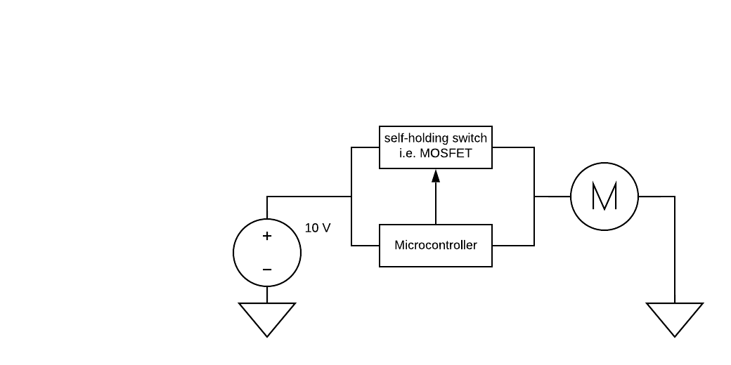
Here is a basic schematic of the problem. The idea is that the switch
should be not conductive at power up so the µC can boot. Then once
triggered by the µC, the switch should stay conductive until power is
cut.
I would consider a latching (polarized) magnetic relay.
Please log in before posting. Registration is free and takes only a minute.
Existing account
Do you have a Google/GoogleMail account? No registration required!
Log in with Google account
Log in with Google account
No account? Register here.