
Hello everybody,

I´m a total Noob - please be tolerant with me, I go straight to my
question:

I added a circuit diagram, on the upper right of it there is a choke
with 2.5 mH directly behind the power input.

But I cannot grasp what kind of Choke that actually represents, all I
have is the symbol of an air choke and the value of it. I have no clue
what that actually would be for me to order in an electronic shop.

I made day-long research on the internet and learned a lot about chokes.

However, what kind of choke I could use to finish my project, I did not
learn.

The circuit I have from a book of the 90´s. It was designed to replace
an old 3-stage Tube-Aplifier with at these times more modern parts.
There is not much on the Internet when it comes to making an Op-Amp with
discrete parts.

Of course I could make one with a LM 741, but I have a particular
interest in that design, is is a vintage design being the key component
of a device presented in the book.

I´d be also glad for every comment on the circuit, what it does and what
range of frequencies you would expect it should deliver on the output.


Thanks for any comments,

Lead
Attached files:
-

circuit.jpg
28 KB
Hallo Zusammen!

Bin voll der Anfänger/Neuling in diesem Forum - dachte ich könnte hier
zweisprachig posten, nun, auf die Gefahr hin dass ich mich hier noch
mehr blamiere, stelle ich gleich die Frage zuerst:

Auf dem Schaltplan oben rechts am Stromeingang ist eine "Induktivität"
zu sehen.

Aber welches physische Bauteil repräsentiert das Symbol eigentlich, ich
habe nur das Luftspulen-Symbol und den Wert von 2.5 mH, was genau das
sein soll weiß ich nicht.

Ich habe tagelang im Internet gesurft um eine Antwort zu finden und
dabei Induktivitäten-Grundlagen gelernt.

Nur welches Bauteil (Filter-Spule, Drossel, Pi-Filter) ich konkret
nehmen könnte habe ich nicht herausfinden können.

Die Schaltung habe ich aus einem Buch von den 90er Jahren. Der
Schaltkreis soll einen alten Röhrenverstärker mit den damals noch
moderneren Komponenten ersetzen. Im Internet gibt es nichts an Info,
wenn es darum geht einen OP Amp aus diskreten Teilen zu bauen.

Natürlich könnte ich auch einen LM 741 nehmen, aber mir geht es um was
anderes, es ist ein Retro-Nachbau von einem im Buch vorgestellten
Projekt. Und ist doch interessant für einen Anfänger wie mich sowas aus
Transistoren zusammen zu basteln.

Vielleicht will hier jemand kommentieren, was die Schaltung macht und
was beim Ausgang herauskommen sollte. Ich habe zwar ein DSO Shell und
Multimeter, das ist aber auch schon alles.

Für Kommentare/Hilfe wäre ich sehr dankbar,

Güße von Lead
A standard RF choke will do here. Even the value is open for changes, as
its only purpose is to suppress RF injected into the power supply.

E.g. a 470µH choke will do the same job.

Suche dir irgendeine HF-Drossel, der Wert von 2,5mH ist reichlich hoch
gegriffen. Eine 470µH Drossel tuts hier genauso.
Attached files:
-

inductor.PNG
12 KB
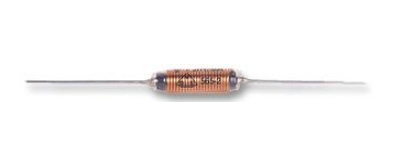
Thanks for answering, I found one as shown in the picture, it should do
the job.

Danke für die Antwort, habe den hier gefunden, muss ja keine
Ringkern-Spule sein.
Please log in before posting. Registration is free and takes only a minute.
Existing account
Do you have a Google/GoogleMail account? No registration required!
Log in with Google account
Log in with Google account
No account? Register here.