Hi, could someone please help me to try and understand how to convert
the code at this address:

https://fpgaw0rld.wordpress.com/2016/11/21/a-simple-vga-driver-for-fpgas/

to run on a FPGA board with a 50Mhz clock. I have tried to change the
code which is written for a 100Mhz clock to work on a 50Mhz clock
without success (my attached 3 files refer).

Many thanks (please see last version of hsync.v, forgot to put another
line of code back in)
Hi,

it seems you did some miscalculations in vsync.v. but anyways its easier
to make vsync depend on hsync instead calculate it independently. just
take a look at my old vga vhdl source.
Hi Tim and many thanks for your reply.

I had the Back Porch at 29 lines and your code shows it at 33 lines. I
have attached my amended code but still no joy.

Would you be kind enough to upload the vsync.v to what you suggest
should work.

I have also taken onboard your suggestion as outlined in your code, but
before I get into this I would like to know where the code I am using is
going wrong.
Hi again,

unfortunately I upped an old file that was designed to run at 25.175 MHz
and with inverted sync polarities (but out of lazyness i didnt change
the clock name). So I did some modifications to let it run at 50 MHz.
Since the vsync depends on hsync, I just had to scale the horizontal
pixel timings by 50 MHz / 25.175 MHz = ~1.986.
The miscalculation in your vsync I mentioned was all about the 525 lines
and the counting values.

To get that thing working all you have to do is to remove that clock
divider in your top module VGA640x480.v and use the same timings like
https://fpgaw0rld.wordpress.com/2016/11/21/a-simple-vga-driver-for-fpgas/
or better the corrected one with timing for 525 lines.
Attached files:
-

Horizontal_Scanline.png
3.6 KB -

Vertical_Scanline.png
3.4 KB
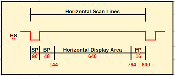
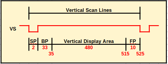
I have attached the amended 3 files: VGA640x480.v, hsync.v and vsync.v

The hsync.v file is exactly the same as the original file from the
website mentioned.

The vsync.v file is also the same, except I have changed the total lines
to 525 and the timings accordingly.

The VGA640x480.v file has the clock divider removed (CLC_50).

I have attached two pictures showing the h and v scans used.

Unfortunately, the code still does not work.
Seems its time to get an oscilloscope and verify the timings.
Are you sure that your constraints are correct?
Just in the process of converting your code to HDL in Verilog to see if
I can get it to work.

I do have an example VGA_TEST program (1024*768 60Hz VGA) that works
(came with my development board) but this code is a bit to complicated
for me yet. I have used the pins on the board assigned to this code on
my code.
If you use SVGA resolution 800x600 @ 72 Hz you could use that 50MHz
clock directly as pixel clock, just change the constants in my vhdl
snippet to:
1 | -- Video Parameter |
2 | constant HTOTAL : integer := 1040; |
3 | constant HSYNC : integer := 120; |
4 | constant HBACK_PORCH : integer := 64; |
5 | constant HACTIVE : integer := 800; |
6 | constant HFRONT_PORCH : integer := 56; |
7 | constant VTOTAL : integer := 666; |
8 | constant VSYNC : integer := 6; |
9 | constant VBACK_PORCH : integer := 23; |
10 | constant VACTIVE : integer := 600; |
11 | constant VFRONT_PORCH : integer := 37; |
12 | constant HPOLARITY : STD_LOGIC := '1'; -- (1 = POSITIV, 0 = NEGATIV) |
13 | constant VPOLARITY : STD_LOGIC := '1'; -- (1 = POSITIV, 0 = NEGATIV) |
Finally, got it to work in 640x480 and 800x600 modes using your code. I
have attached the code, hope I've converted it right but it does seem to
work.

The pins must have been correct because I didn't change them. However, I
have since increased the range of RGB colours from RGB(3:0) to
(5:0),(6:0),(5:0) due to the layout of my development board.

Possibly the timings were out in my original code. I will try to figure
that one out though.

Many thanks for your help with this Tim, very much appreciated.
Please log in before posting. Registration is free and takes only a minute.
Existing account
Do you have a Google/GoogleMail account? No registration required!
Log in with Google account
Log in with Google account
No account? Register here.