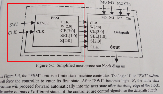
Hello, I am trying to create a Finite State Machine to control the
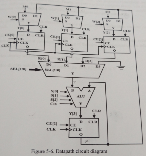
outputs specified in image 1. I have already created the Datapath module
as shown in image 2. The instructions in image 1 are what is confusing
me. I don't have a clear idea on what it wants. Any clarification would
be much appreciated. I am also including the beginning of my FSM
verilog.
1 | module fsm(reset, clk, s, sel, ce, w, clr);
|
2 | input clk,reset;
|
3 | output clr;
|
4 | output [2:0] w;
|
5 | output [2:0] ce;
|
6 | output [1:0] sel;
|
7 | output [2:0] s;
|
8 |
|
9 | reg clr;
|
10 | reg [2:0] w;
|
11 | reg [2:0] ce;
|
12 | reg [1:0] sel;
|
13 | reg [2:0] s;
|
14 | reg [2:0] cs,ns;
|
15 | parameter
|
16 | s0=0;
|
17 | s1=1;
|
18 |
|
19 | always@(posedge clk or posedge reset)
|
20 | begin
|
21 | if (reset==1) cs<=s1;
|
22 | else cs<=ns;
|
23 | end
|
24 |
|
25 | always@ (cs or start)
|
26 | begin
|
27 | case(cs)
|
28 |
|
29 | endcase
|
30 | end
|
31 |
|
32 |
|
33 | always @ (cs)
|
34 | begin
|
35 | case(cs)
|
36 |
|
37 | endcase
|
38 | end
|
39 | endmodule
|