PI loop filter in Verilog

#5323678
Rate this post
• ▲ useful
▼ not useful
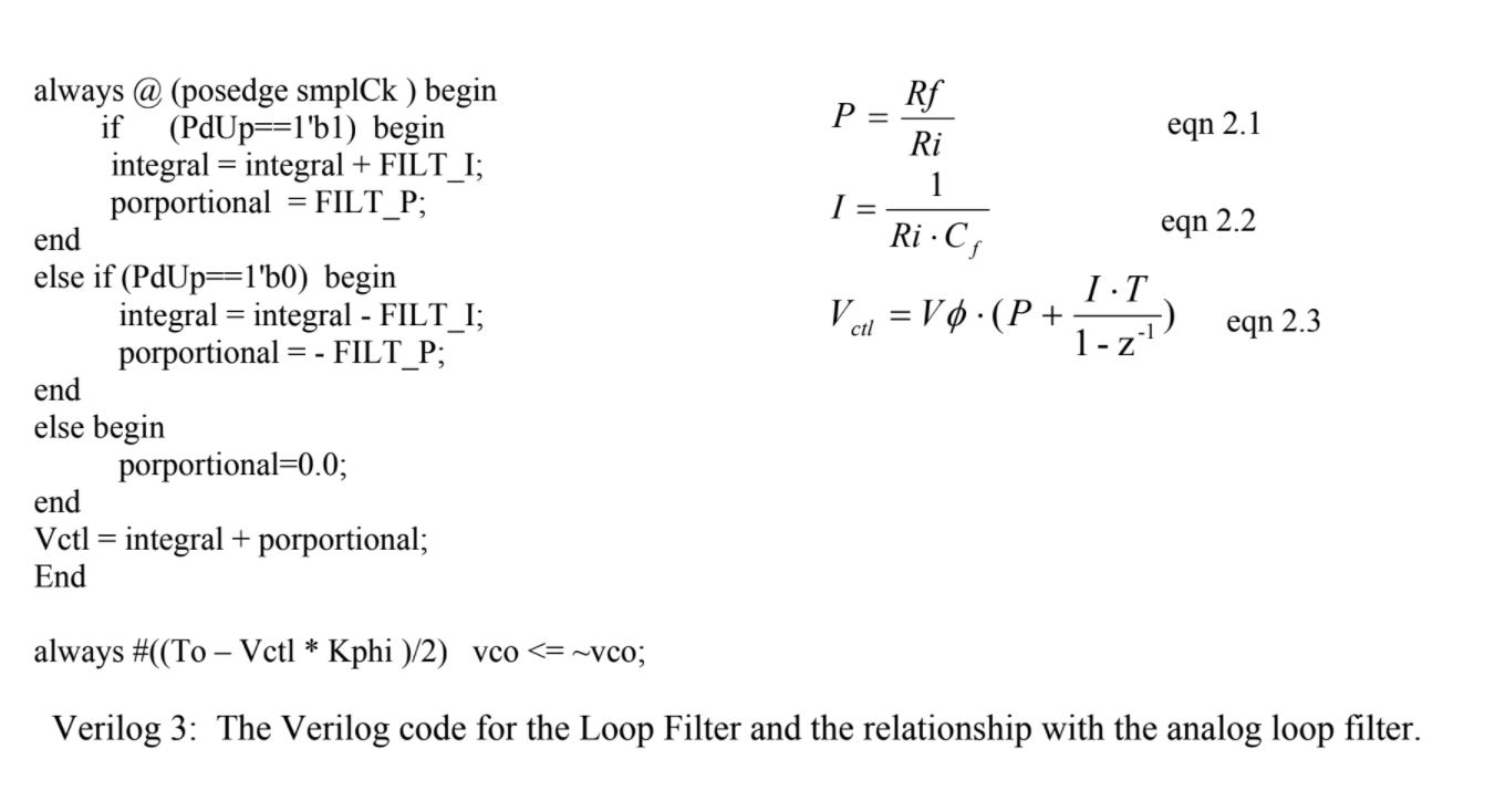
From what I understand about PID controllers is that the integral 
portion is just an accumulator. Which is why its integral = integral + 
FILT_I. Each time it adds the current value to the 
accumulator(integrator).

The formulas on the right are for the analog filter in the article, 
which is made with an op amp. I'm not sure you're going to find a 
correlation between the two.

Just my two cents.
OP #5327071
Rate this post
• ▲ useful
▼ not useful
Hello, There are two variables, integral and proportional when clk=1 
then
integral decreases ,when clk=0 then it decreases.

proportional toggles from negative to positive with the FILT amplitude.

and both of them goes into vtcl with is the factor controlling the 
period of the VCO.

how this logic represnt PID loop filter?

Thanks

Reply

Note: the original post is older than 6 months. Please don't ask any new questions in this thread, but start a new one.

Formatting
  • [c]C-Code[/c]
  • [vhdl]VHDL-Code[/vhdl]
  • [code]code in other languages, ASCII drawings[/code]
  • [math]formula (LaTeX syntax)[/math]
  • [[Title]] – link to an article
  • Link to another post: right-click its post ID (#8078628), copy the address, paste it into the text

More about formatting

Post long source code as an attachment, not in the text.

Already registered? Log in

Not shown to anyone. We send you a link; your post appears once you confirm it there.

By submitting you create a free account and accept the terms of use.