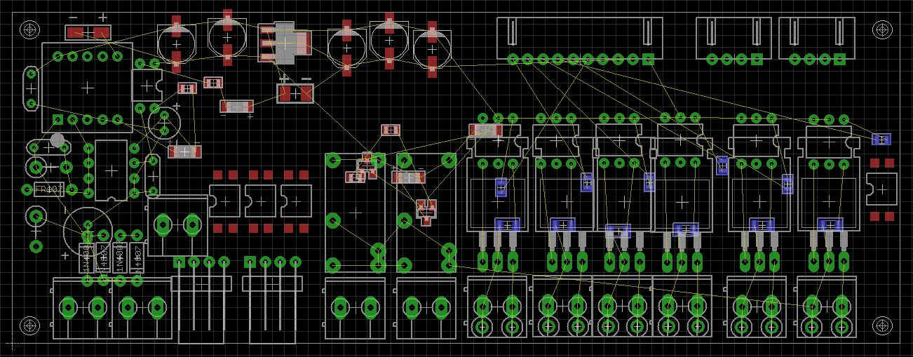
I am working on a project which involves micro-controller and switches
(triacs and EM relays).(I found these pieces
here:http://www.kynix.com/Product/Cate/35.html)

Due to size constraint, I need to stack one over the other. Here is
unfinished relay and triac board which will go on top of
micro-controller board of the same size:

http://i.stack.imgur.com/IpJ6a.png

PCB description: 220V to 5V offline switcher on the left. It has a
switching frequency of 65 kHz. Two transistor driven electro-mechanical
relays in between and 6 optically isolated triacs on the right. There
are a few connectors for optional sensors.

I have given 4 holes in corners so that I can use spacers and nut bolts
to put the two PCBs together. Electrical connection between the two will
be made using either a cable or header pins (yet to be decided).

As such what should be the minimum distance between the two PCBs so that
high voltage or whatever noise is there in ac lines don't disturb the
delicate electronics below?

Is there something which I should use in between to provide added safety
to my micro-controller board?

I was thinking of some plastic sheet the same size of PCB or two plastic
sheets with a thin metal foil sandwiched between them but I am not sure
whether they will have any impact or not.

Any suggestions regarding this will be much appreciated.

Thanks
Attached files:
-

IpJ6a.png
38 KB
Please log in before posting. Registration is free and takes only a minute.
Existing account
Do you have a Google/GoogleMail account? No registration required!
Log in with Google account
Log in with Google account
No account? Register here.