Hi everyone,
I'm supposed to write code for simple frequency meter. What it is
supposed to do is:
when you press button it should measure frequency of input signal based
on 1Hz clock signal so the outcome won't need any dividing to get
frequency. Basically measuring input signal "peaks" in 1s period. The
result must be shown in kHz on 2 7digt displays (30-40kHz measurement).
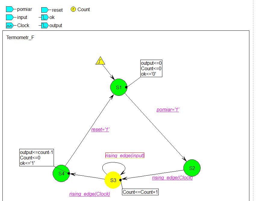
I thought I'm gonna use state machine diagram but even if it is
compileable in Active HDL, I get a "Error (10822): HDL error at
Termometr_F.vhd(69): couldn't implement registers for assignments on
this clock edge" in Quartus...
Is there a way to implement this diagram in Quartus software? I've tried
another method: dividing input signal by 2 to get a gate signal and then
counting pulses but dividing is also not compilable without using
floating point operations for which I don't have liblaries for...
Here is the code:
library IEEE;
use IEEE.std_logic_1164.all;
use IEEE.std_logic_arith.all;
use IEEE.std_logic_unsigned.all;
entity Termometr_F is
port (
Clock: in STD_LOGIC;
input: in STD_LOGIC;
measure: in STD_LOGIC;
reset: in STD_LOGIC;
ok: out STD_LOGIC;
output: out INTEGER);
end Termometr_F;
architecture Termometr_F_arch of Termometr_F is
signal Count: INTEGER;
type Termometr_F_type is (
S1, S2, S3, S4);
signal Termometr_F: Termometr_F_type;
begin
Termometr_F_machine: process (Clock)
begin
if Clock'event and Clock = '1' then
case Termometr_F is
when S1 =>
output <= 0;
Count <= 0;
ok <= '0';
if measure='1' then
Termometr_F <= S2;
end if;
when S2 =>
if rising_edge(Clock) then
Termometr_F <= S3;
end if;
when S3 =>
Count <= Count+1;
if rising_edge(input) then
Termometr_F <= S3;
elsif rising_edge(Clock) then
Termometr_F <= S4;
end if;
when S4 =>
output <= count-1;
Count <= 0;
ok <= '1';
if reset='1' then
Termometr_F <= S1;
end if;
when others =>
null;
end case;
end if;
end process;
end Termometr_F_arch;
Thanks in advance
Attached files:
-

graph.jpg
45 KB
Did you see in the synthesizers user guide that the synthesizer is able
to translate such a thing into hardware:
1 | if Clock'event and Clock = '1' then -- This here is a rising_edge already |
2 | ....
|
3 | if rising_edge(Clock) then |
4 | ....
|
5 | if rising_edge(input) then |
6 | ....
|
7 | elsif rising_edge(Clock) then |
8 | ....
|
I did never ever see a synthesizer able to translate such a construct
into hardware. Indeed the only hardware inside a FPGA you can use is
LUTs (for logic) and simple D-flipflops.
And a simple D-flipflop does not have multiple clock inputs like that
you want to have. To keep things short: kick that code away and look how
everybody in the world writes a clocked process. Yes, there must be
only 1 clock in the process , because the D-flipflop inside the FPGA has
only 1 clock input.

BTW:
Why don't you use human readable states like (RESET, IDLE,  MEASURE,
DISPLAY) instead of that meaningless S1...4?
Please log in before posting. Registration is free and takes only a minute.
Existing account
Do you have a Google/GoogleMail account? No registration required!
Log in with Google account
Log in with Google account
No account? Register here.