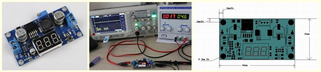
Features
1.With voltage meter display;voltage meter error of ±0.1V;the range
among 0~40V. (note: to ensure the voltage meter accuracy, please make
sure that the input voltage is 4.2V or more).
2.Voltage meter can be closed by long pressing button(minimum power
loss).
3.The range of input voltage is 4.2~40V and output voltage is1.25V~37V
,which are continuously adjustable.(The input voltage must 1V higher
than output voltage)
4.Maximum output current can be as high as 3A,but normal and stable
working current is2A.
5.Use 150KHZ internal oscillation frequency,which is belong to the
second generation of switch voltage regulator with low consumption and
high efficiency.

Where to use:1.experiment teaching 2.temporarily set up power supply in
the outdoor 3.car(audio, electric fan)power supply

What is special:LM2596 Step Down Power Module design based on XL2596 as
main control chip,attached digital tube to display voltage at that time
to highlight smart function. What’more, schottky diode provides
protection of reverse connection.

Testing Results
Because the starting voltage is 4.2V, when testing you should set the
input voltage 4.5V and the output voltage 1.4V. ICStation Team test it
on the digital oscilloscope and the result shows that the actual testing
of the product is in accordance with the description.
Attached files:
-

152.jpg
37 KB
Please log in before posting. Registration is free and takes only a minute.
Existing account
Do you have a Google/GoogleMail account? No registration required!
Log in with Google account
Log in with Google account
No account? Register here.