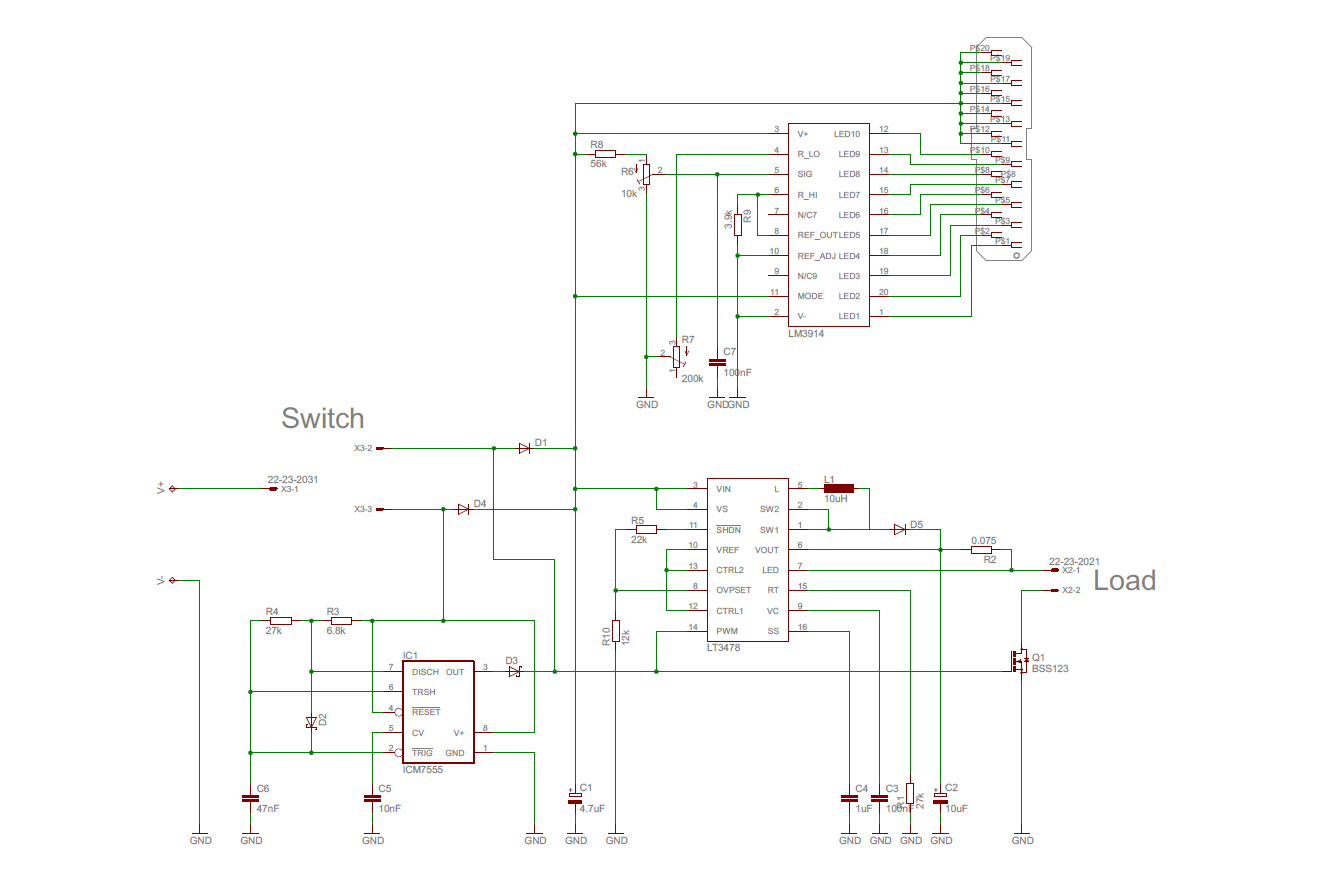
HINT: You can probably ignore the whole circuitry at the top of the
attached image. I highly doubt it is of relevance to my problem.

Hello,
I've got a problem with this project. It is supposed to be a driver for
a high-powered LED (bottom right IC) with a dimming function using a PWM
generator (bottom left IC, equivalent to a regular NE555). I also added
something to monitor my input voltage level (top IC) since it'll be
running off a battery pack.

The whole things works quite brilliantly. No excessive heat build-up on
any of the parts except the load resistor which I substituted my LED
with.

------ THIS IS THE PROBLEM ------

The dimming is not working because the gate pin of my nMOS is being
pulled to approx. 11V (input voltage is around 13.2V). The 555 is
producing a rect signal of 4.8V at 1kHz (22% duty) at its OUT pin but
immediately after D3 I'm meassuring roughly 11V. The AC signal is still
there, superimposed on a 10V DC signal, with a 0.8V amplitude, same
frequency, same duty cycle - but of course the nMOS is permanently open
under those conditions.

I have tried pinpointing the source, even cut off the connection to the
LT3478's PWM pin because I suspected it might be supplying that voltage
level, but it didn't.

None of the diodes D1, D3 or D4 are anywhere near their reverse
breakdown voltages. I meassured the MOSFET's on/off resistances to
confirm whether or not it may be broken but all is in order.

I probed my PCB for hours, looking for any printing errors or
short-circuits and found none. Everything looks exactly as I designed
it.

------ END OF WALL OF TEXT ------

I'm pretty lost here. I'm doing electronics as a hobby and I never
studied this stuff so I might be missing something elementary. Or maybe
this project hates me.

If you see something that could be the cause or have an idea what I
could try to locate it, please share it. Anything, and I mean ANYTHING,
is better than staring at this board for another week every evening.
Attached files:
-

shematic.png
68 KB
That did the trick! Much appreciated. I found a via on that signal,
scratched off some nearby solder mask to open a ground "pad" and
soldered a 56k Ohm resistor between the two. (It was the only SMD
resistor I had lying around at the time as I'm not usually doing this
small-scale stuff - the project demands it though.)
If anyone feels like explaining why this solved my problem or why I even
had it in the first place, go ahead.
Please log in before posting. Registration is free and takes only a minute.
Existing account
Do you have a Google/GoogleMail account? No registration required!
Log in with Google account
Log in with Google account
No account? Register here.