EmbDev.net

Forum: FPGA, VHDL & Verilog Shift problem


von Enrico M. (harrym)


Rate this post
useful
not useful
Hello,
I am just a college student, I am trying to improve my knowledge of 
Verilog :) Now I am working with an Altera DE0-Nano. What I would like 
to achieve is pretty simple: a shift register that shifts to the left 
with one button and to the right with another one. My first draft was 
the following one, but it did not work.
1
module led_shift(UP, DOWN, RES, CLK, LED);
2
input UP, DOWN, RES, CLK;
3
output reg [7:0] LED;
4
reg [7:0] STATE;
5
6
always@(negedge DOWN or negedge UP or negedge RES)
7
begin
8
    if(!RES)
9
    begin
10
        STATE <= 8'b00010000;
11
    end
12
    else
13
    begin
14
        STATE <= UP ? STATE>>1 : STATE<<1;
15
    end
16
end
17
18
always @ (posedge CLK)
19
begin
20
    LED <= STATE;
21
end
22
endmodule
The problem was, that it was not clear for the synthesizer to know how 
to control STATE with the 3 asynchronous control signals, so I was told 
to use the technique of clock domain crossing. To simplify more, I 
decided to work with only the left shift, and this is the second draft.
1
module led_shift(UP, DOWN, RES, CLK, LED);
2
3
  input UP, DOWN, RES, CLK;
4
  output reg [7:0] LED;
5
  reg [7:0] STATE;
6
  reg pre_sync_UP, sync_UP;
7
8
  
9
  always @(posedge CLK) begin
10
    if(!RES) begin
11
      LED = 8'b00000001;
12
    end
13
    else begin
14
      pre_sync_UP <= UP;
15
      sync_UP <= pre_sync_UP;
16
      LED <= STATE;
17
    end
18
  end
19
  
20
  always@(sync_UP or pre_sync_UP) begin
21
    if(sync_UP && !pre_sync_UP) begin
22
      STATE <= LED << 1;
23
    end
24
    else begin
25
      STATE <= LED;
26
    end
27
  end
28
29
  
30
endmodule
(Istead of
1
sync_UP && !pre_sync_UP
 I also tried the xor, but it did not work)
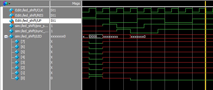
Unfortunately it does not work at all, after putting the RES at 1, it 
seems that the shift is always performed, even without pressing the 
button. I can not see why, though. Someone can help me?
Thanks!

von bko (Guest)


Rate this post
useful
not useful
probably the problem with your  button is, it bounce
http://www.fpga4fun.com/Debouncer.html

von Enrico M. (harrym)


Rate this post
useful
not useful
Thank you for your answer. I also thought at a debouncer, at first, but 
the datasheet of the board says that "The DE0-Nano board contains two 
pushbuttons shown in Figure 3-3. Each pushbutton is debounced using a 
Schmitt Trigger circuit, as indicated in Figure 3-4. The two outputs 
called KEY0, and KEY1 of the Schmitt Trigger devices are connected 
directly to the Cyclone IV E FPGA. Each pushbutton provides a high logic 
level when it is not pressed, and provides a low logic level when 
pressed. Since the pushbuttons are debounced, they are appropriate for 
using as clock or reset inputs".

Moreover, the hardware debouncer works properly, in another small 
project i did not have bouncing problems.

I am afraid that something is wrong with my code.

von bko (Guest)


Rate this post
useful
not useful
What does the simulation tell you?
Do you have a testbench?

von Enrico M. (harrym)


Attached files:

Rate this post
useful
not useful
I tried a simulation last evening with Modelsim.
The behaviour in the simulation is weird, but follows what I see on the 
board. I cannot understand why the value of the output becomes X after 
taking off the reset signal, maybe is for this line:
1
else begin
2
      STATE <= LED;
3
    end

von P. K. (pek)


Rate this post
useful
not useful
From a verilog point of view, I cannot say much, as I'm not very 
familiar with it, however:

- Registers presync_up and sync_up stay undefined well after the reset,
  maybe you should reset them, too.
- I'd ad the Signal state to the waveforms as well (see more).

So I think it is a mere propagation of undefined signal values.

von Enrico M. (harrym)


Attached files:

Rate this post
useful
not useful
Thank you very much, that was the problem! I still can not understand 
why I have this problem, I thought that everything would have been 
solved by itself at the first press of the UP button. I will study it 
more!
As attachment there is the full working program, in case someone want to 
see it in the future.

Thanks again!

Please log in before posting. Registration is free and takes only a minute.
Existing account
Do you have a Google/GoogleMail account? No registration required!
Log in with Google account
No account? Register here.