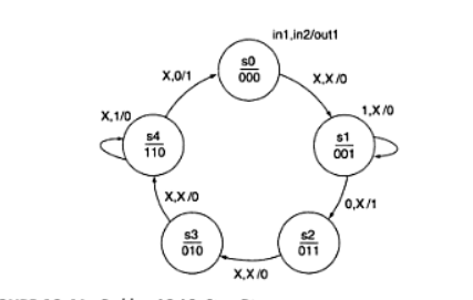
I need help with this state Diagram. I think I can write the code for it
but im a little confused on what the x,x/0 means. Any help would be
greatly appreciated.
Attached files:
-

Diagram.png
13 KB
x,x -> state transition without constraints
0,x -> state transition only when in1=0
...
LIBRARY ieee;
USE ieee.std_logic_1164.ALL;

ENTITY number8 IS
PORT(
CLK        : IN BIT;
IN1, IN2     : IN BIT;
OUT1            : OUT BIT);
END number8;

ARCHITECTURE circuit OF number8 IS
TYPE STATE_TYPE IS (S0, S1, S2, S3, S4, S5, S6, S7);
SIGNAL state   : STATE_TYPE;

BEGIN

PROCESS(CLK)
BEGIN
IF (CLK'EVENT AND CLK = '1') THEN
CASE state IS
WHEN S0 => state <= S1;
OUT1    <= '0';
WHEN S1 =>
IF IN1 = '1' THEN
state <= S1;
OUT1  <= '0';
ELSIF IN1 = '0' THEN
state <= S2;
OUT1  <= '1';
END IF;
WHEN S2 => state <= S3;
OUT1    <= '0';
WHEN S3 => state <= S4;
OUT1    <= '0';
WHEN S4 =>
IF IN2 = '1' THEN
state <= S4;
OUT1  <= '0';
ELSIF IN2  = '0' THEN
state <= S0;
OUT1  <= '1';
END IF;
WHEN S5 => state <= S0;
WHEN S6 => state <= S0;
WHEN S7 => state <= S0;
END CASE;
END IF;
END PROCESS;
END circuit;


Here is the code I came up with. does it look ok. It compiles fine but I
havent ran a simulation yet.

Thanks for the input Flomobile!! That was exactly what I needed to know.
I realized that I still have the Library on there when I didnt use
STD_logic.

ooops..
Attached files:
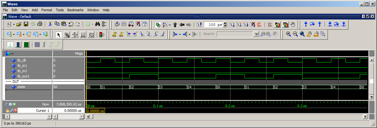
You also have some superflous states at the moment (S5, S6, S7).
But the simulation looks nice.
And with some formatting the code looks also nice:
1 | entity number8 is |
2 | port( |
3 | CLK : in bit; |
4 | IN1, IN2 : in bit; |
5 | OUT1 : out bit |
6 | );
|
7 | end number8; |
8 | |
9 | architecture circuit of number8 is |
10 | type STATE_TYPE is (S0, S1, S2, S3, S4, S5, S6, S7); |
11 | signal state : STATE_TYPE; |
12 | |
13 | begin
|
14 | |
15 | process(CLK) |
16 | begin
|
17 | if (CLK'event and CLK = '1') then |
18 | case state is |
19 | when S0 => state <= S1; |
20 | OUT1 <= '0'; |
21 | when S1 => |
22 | if IN1 = '1' then |
23 | state <= S1; |
24 | OUT1 <= '0'; |
25 | elsif IN1 = '0' then |
26 | state <= S2; |
27 | OUT1 <= '1'; |
28 | end if; |
29 | when S2 => state <= S3; |
30 | OUT1 <= '0'; |
31 | when S3 => state <= S4; |
32 | OUT1 <= '0'; |
33 | when S4 => |
34 | if IN2 = '1' then |
35 | state <= S4; |
36 | OUT1 <= '0'; |
37 | elsif IN2 = '0' then |
38 | state <= S0; |
39 | OUT1 <= '1'; |
40 | end if; |
41 | when S5 => state <= S0; |
42 | when S6 => state <= S0; |
43 | when S7 => state <= S0; |
44 | end case; |
45 | end if; |
46 | end process; |
47 | end circuit; |
Duke
Thanks Duke.. I tried copying it from quartus but it wouldnt let me
paste it on to the thread. But yes my code looked like yours
(formatting). Thanks for running the simulation and taking the time to
look at my code I really appreciate it.
Please log in before posting. Registration is free and takes only a minute.
Existing account
Do you have a Google/GoogleMail account? No registration required!
Log in with Google account
Log in with Google account
No account? Register here.